Thank you for taking the time to respond. I would very much like to submit a video, unfortunately, I do not have those posting privileges. Should you be of any assistance there kindly let me know.
Incidentally, would you mind sharing what type of oil catch can set up that you are using? For instance, is there some type of medium at the top of The canister to aid in separation of oil from the air?
Hi Kevin,
My engine has the original wire gauze oil separator, P/no C-44410, to which I added an extra disc of fine wire mesh(made from a S/S sink drain). There is plenty of room below the pig snout. No aftermarket catch can.
1 Like
Just post it on youtube, don’t need anything special - apart from vacuum gauge for $15 minimum… Example/reference - below:

Dave, thank you again for all of your contributions. May I ask where you purchased the following timing cover vent plug/combination breather. Also assuming that is an adjustable rubber grommet?

The photo you show is home-made, and is indeed a 1inch expandable plug, with a piece of 1/8 threaded pipe inserted with a silver-soldered nut on one end, followed by a 90 degree elbow/adaptor and a 3/8 hose fitting.

This has not been used yet, and I made it in case the first breather failed.
The first breather is an OE timing chain cover plug with a hole drilled through it so a 90 degree barbed elbow would be a tight fit. It is in my car, working fine.

The next photo shows (Using a mirror) the connection to the front of the engine.
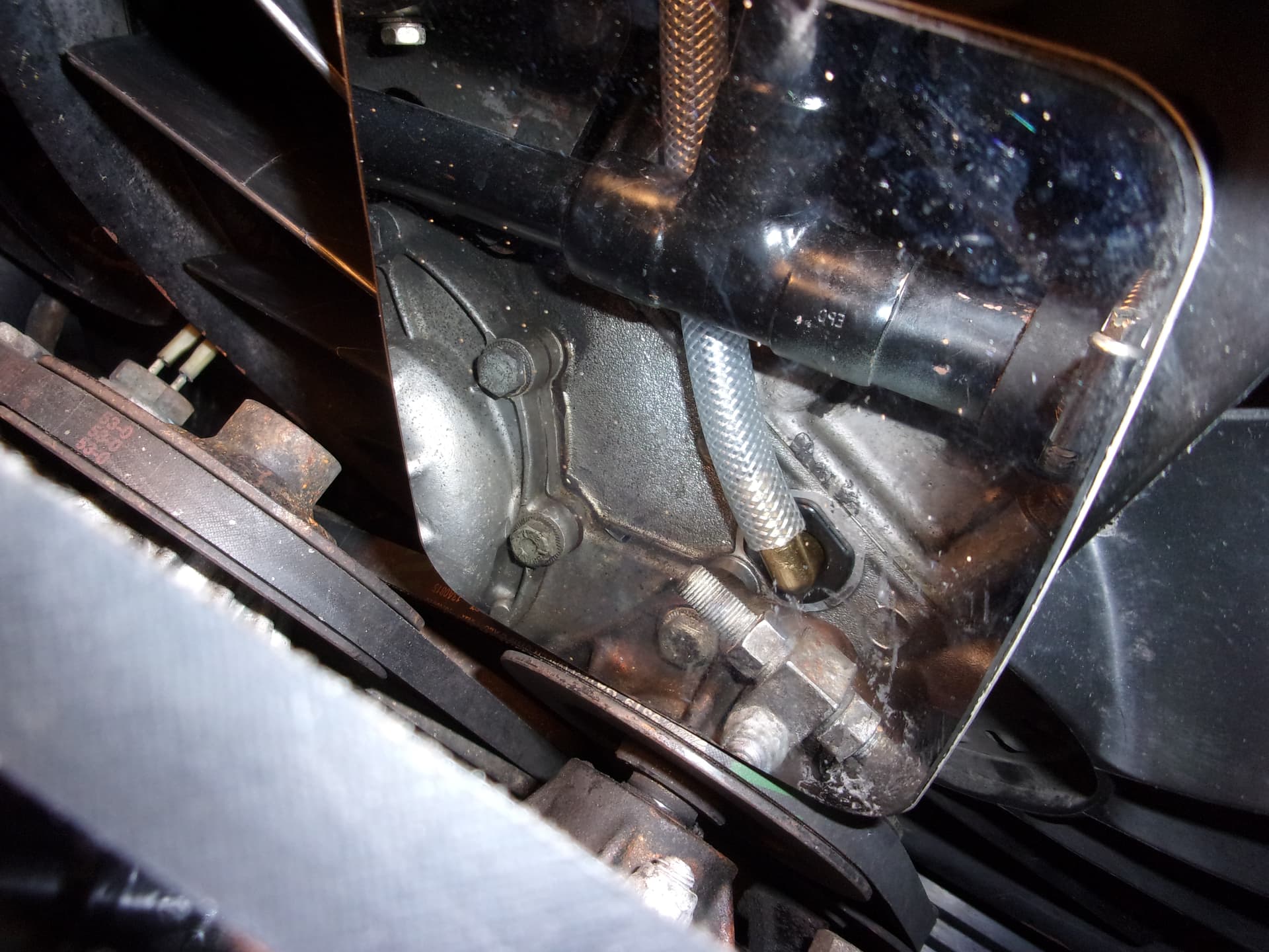
The final photo shows the fresh air intake which is connected to the clean side of “A” bank air cleaner. Should any pressure build up in the crankcase, it will dump to the air cleaner, although I have not seen any evidence of that happening.

Thank you very much again for taking the time to post. I like the prototype solution better. Curious, having some difficulty sourcing a 1 inch plug, success in sourcing a 3/4 inch plug. Also, you are threading a nut onto a 1/8 NPT?
Search for “1inch expandable rubber plug” Dorman 02600 available at any decent FLAPS, and, of course, Amazon.
The big box hardware stores carry kits to make tablelamps, in the electrical lamp section. The kits contain different lengths of 1/8 pipe nipples, and the nuts that fit the 1/8x27 thread.
Search Lowes P/no’s 47808, 46935 ,905L, LP1.
This assumes you are in the US, which we still do not know.
One further small point- I am not trying to persuade you to manufacture anything. My initial response to this thread was to figure out why there is so much oil around your throttle bodies. YMMV!
PCV systems are fairly straightforward. Install a fresh air inlet on one side of the engine. Apply a low pressure area (largely controlled by the PCV valve) to the other side of the engine to extract the high pressure blowby and as an added benefit, extend the life of oil seals.
It was a tried and proven system in 1975 when Jaguar introduced the FI V-12, but Jaguar will be Jaguar. Just as they did with the transmission mount, they thought they had a solution looking for a problem, and ended up over engineering the solution.
The manufacturing tolerances in 1975 were extremely loose by today’s standards. The V-12 is prone to significant blowby and as such the infective PCV solution designed by Jaguar proved highly ineffective.
Over the years, Jaguar V-12 owners have designed their own solutions.
Personally, because of the heavy blowby of these engines, I don’t believe a fresh air inlet is necessary when designing a PCV solution. The volume of blowby makes the fresh air intake somewhat redundant.
Attaching full vacuum to the crankcase is not recommended. Therefore any designed system should have a method of applying consistent low pressure to the crankcase. This methodology can be a PCV valve in series or a way of diverting some full engine vacuum away from the crankcase.
There is really no single method of accomplishing this. Owners of older Jaguar vehicles have been notorious for designing various diverse solutions to problems as they arise.
My solution, which includes a home built Air/Oil separator, is no different from some. More complicated Yes, but probably as effective as most.
1 Like
Bernard –
Thank you very much for taking the time to respond, very familiar with your website and can appreciate all of the work that you chronicled over the years. I just completed the restoration of a Rolls-Royce Silver Shadow, the Jaguar XJS will be the final.
I have uploaded the following video which provides crankcase pressure data. I have basically plumbed in a vacuum gauge into the dipstick orifice. At idle, with a complete 17 inches of vacuum drawn on an oil separator connected directly to the pig snout via the manifold crossover pipe, the gauge reads 1 inch of vacuum. Clearly, air is being scavenged through the crank, rope seal etc. The video will show that upon a snap acceleration, crankcase pressure builds to three psi. I should add that I no longer have leaks at the crank or vacuum seal after drawing vacuum on the breather at idle, or a gentle progression of acceleration that preserves overall system vacuum.
Obviously, with very brisk acceleration the system vacuum drops to around 5 to 10 inches, and the associated blow by brings the crank case pressure to around 2 to 3 psi. As you suggested in your message, perhaps I could add a second PCV device that will be deployed in these instances. Perhaps I could add a second PCV device to the timing cover inspection grommet that could be triggered with a solenoid driven by the full enrichment throttle switch (Half kidding).
FYI, the gauge shows engine temperature, system voltage and oil pressure in bar units. The gauge is extremely reliable, and I observe about 82°C at idle and at highway speeds. I’m very pleased with my Toyota Camry dual fan and shroud assembly.

The following is data obtained from a manufacturer of custom PCV systems:
“On engines using the factory designed crankcase ventilation system (a PCV or “positive crankcase ventilation” system), we typically measure peak crankcase pressures on the order of 2.5 to 6.0 psi when the engine is in normal running order.”
Source:
Here is the oil catch can I am using. Moroso (85474). Having tried various catch cans on my Volvos, where the turbo can push the manifold pressure up to 15psi, I found the bigger the better, and quality is very important. A valve to empty it is also super convenient.

Thank you very much for taking the time to post, most appreciated. I’m curious as to why the right intake manifold leaking so much as opposed to the right.
Glad to see this is a current discussion again. Greg, Dave and Aristides, I found your original musings. PCV modification sucked, but second attempt succeeded! - #82 by Aristides
This was very good. In the process of installing a PCV system. Last night I put a 3/8" barb through the TC case bung (easy in place – awl and reamer), connected to airbox A as in Dave’s pics. A generic PCV valve (Is there such a thing? I would love to find a table of cheap PCV valves and their flow characteristics) is in the piggy snout. Currently connected to the inter-bank “Y” pipe, which also tees to a greatly-simplified charcoal canister (generic GM) system. In the process of adding a catch can next to the charcoal canister in the LF wheel well. That’s ready, just got to plumb in the hoses. That’s all old news here. New content: What about a ball valve to control flow to the PCV valve? If you get a floppy one (e.g. original Jag PCV), just vary the flow until you get the desired 1" Hg at idle on the dipstick (or oil cap - nice one, Dave). This: https://www.amazon.com/Horiznext-Brass-Valve-Water-tubing/dp/B07X2G5LKR?th=1
Sort of like the Toyota heater valve with a choke cable that I’ve got in front of the AAV ![]()
1 Like
Once you set the ball valve, remove the handle. Easier than fiddling with tiny-orifice restrictions in the PCV hose (been there with the stock Jag one – it raised idle ~150RPM unrestricted).
PCV solution is in place and I’m very happy with it. The AC Delco PCV valve # 19313317 is pulling 1" Hg (measured at dipstick tube) with ball valve open at about 45 degrees. Adjustable PCV would be nice, but this is cheaper ![]()
Tested with the original Jag valve, and that pulls about 6" Hg with all else being equal. Reports that it flows a lot more than most “generic” PCVs are true.
I’ll put a hole with a bung in the undertray under the catch tank for easier drain access. Some pics:


Thank you very much for this contribution, it’s most appreciated. By the way, I’m very impressed with your catch can set up, can you elaborate? Was this something that you purchased off the shelf or created?
As we’re sharing, here’s my pcv and catch can system. Trying catch cans on my past turbo Volvos, i found bigger is better. I am using a Moroso can. Also using an adjustable pcv valve. One setting is for idle, the other setting opens up valve even more once vacuum increases a few inHg above idle setting (cruising).


1 Like
Very neat installation Greg!
1 Like
@Kevin_Ritter Catch can was an Amazon special. Just POC at this point. Gregma’s is much nicer. Might upgrade later. https://www.amazon.com/gp/product/B0BQ9VC1KZ/
@gregma Good idea on using the space in front of the radiator for the catch can! I keep forgetting about that real estate. Nice job on the non-wobbly A-side/TC plumbing. Also a future upgrade for me.