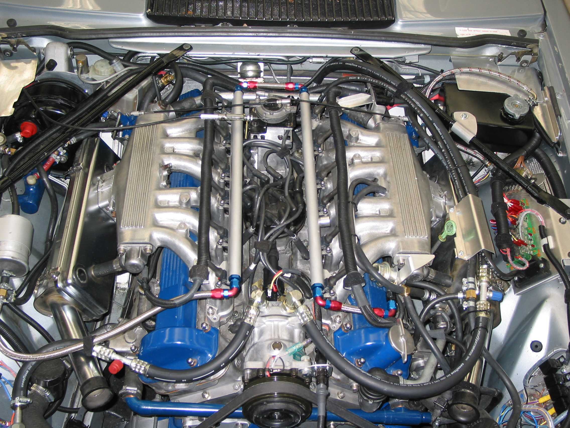
Wow. Would love to see another photo of your engine looking under the bonnet to see all the room up front you saved. That’s impressive nicely done.
I agree, an impressive setup. How did you find the right length serpentine belt?
It does look neater between engine and rad, and it is a “bit” easier to get your hand down there, but still a tight situation. However, those who have had the misfortune to replace a kaput pump with the engine in situ could dream of this setup where the pump is electric and easy to get at.
Luckily it is not too often a pump fails.
It does need bearing in mind the youngest V12 in anybody’s car will be 22 years old now, and most will be more like 32 years old. Long time for a pump seal to last.

1 Like
The belt was one of the easier things to find and fit. I think it was a Gates belt, but we are going back nearly 20 years for this information. The Gates catalog was produced by people with brains. Instead of just having a list of belts with the applicable car model and year, it gave the length in mm and inches. I bought two and one of them was just right.
The belt tension is adjusted with swinging the alternator around its pivot point. Due to the angle between belt and pivot being far from ideal, it takes a lot of adjustment for small change in tension.
When I get to that issue on the rebuilt V12 it will be changed and the fix retrofitted to the coupe engine. The original trial fit of the setup had the belt closer to the engine block with the crossover pipe outside the belt. That meant having to at least partially drain the block and remove the crossover pipe before changing the belt. Not clever ! The belt is now further out, crossover pipe on the inside and lets you change the belt without any other thing being moved.
One thing that was a headache to find was a suitable ribbed pulley to fit the front of the crankshaft.
The obvious choice would be a PK6 or PK8 belt, and I looked at industrial transmission suppliers for a pulley but absolutely nothing doing. In the end the choice was a PK6 pully/damper unit from a Holden V6 engine which was a locally made GM derivative engine. The unit was made in Canada. I have another one for the rebuilt V12, they are quite common on Ebay.
It takes 2 hours work to tear the rubber out of the thing and grind away the spider embedded in it without damaging the useful parts. I had 2 pair of adaptor plates laser cut from 5mm steel 20 years ago to mount the GM item to the OEM damper with the tapered cone fitting. It does take a few hours of lathe work to skim the GM pulley casting and the adaptor plates so it all lines up and runs true.
The replacement pump cover on the coupe engine was made from 10mm aluminium extrusion.
I rough cut it with a bench saw and finished it with a grinding disc, and that took a real long time.
This time around it will be cut out by waterjet, which takes 5 to 10 minutes machine time and costs US$30. At least when I explain to the dubious machine owner how easy it is to do we will have action and cutting. He sees problems while I can see a dead easy job.
1 Like
Love the engine Richard! Those air filter boxes are causing me to turn green. The injector harness is tidy. Fuel rail looks lovely and leak-free. I see a few Saturdays worth of therapy in those intakes finish as well! I’m not sure I understand the serpentine swap. I mean I do, but not your motivation. Regardless, it’s a beautiful piece of work and does transform the front of the engine.
As to dual e-water pumps, I’d think that would have simplified things. Dual pumps could sit in the forward corners. Coolant could go via flexible hoses to separate A and B inlets fabbed up on the water pump block-off plate. Out the end of the water rail straight to the radiator. Use the Davies Craig controller.
Only issue would be the conjoining at the radiator. Two half-size aluminum rads seems the simplest solution. Mirrored design would make the water rail outlets run straight ahead to inboard ( center of car ) rad inlets. While the lower, outboard, rad outlets would be handy to the pumps.
edit:
Hmmm. The inboard header tanks would consume air pathway. Maybe a custom down-flow rad with split header tanks?
Do you have 82c or 88c thermostats?
Beautiful engine and mods, yet you’re still running stock air intake?
Doesn’t seem simple to me. The simplest solution would be a vertical-flow radiator, with two inlets in the upper tank and a single outlet in the lower tank. That’s what the SIII E-type had. I dunno why the push to sideflow radiators, but in the case of the Jaguar V12 it was definitely a change for the worse.
Many modern cars with serpentine belts have spring-loaded tensioners. Why did you decide not to go that route?
My previous post said 88 deg thermostats
I actually had a belt tensioner off the same Holden V6 when I got the damper. Did not look easy to fit it sensibly.
As you know modern engines are designed from the outset with all driven accessories located in such a way as to make a single belt feasible.
I think Davies Craig expected a lot of business from OEM sources when they brought out their electric pumps something like 25 years ago. The local car industry was killed off 3 years ago and I do not think any of them took up the electric pump idea.
There may be a niche market for electric pumps.
Has anybody here seen a popular car using an electric pump ?
No mistake, a standard radiator with the crossover returning to the inlet side of the pump which is down near the exit side of the rad.
One day, or one Saturday morning therapy session I should say, might take a look at fitting an aluminium rad. I doubt it works any better but for sure will be lighter.
That raises a point:
When the brass rad plugs up you can have it rodded, or recored, and get back to 100% efficiency. That does not look possible with an aluminium one.
However, last time I had a recore on my coupe the cost was about the same as buying a new Chinese aluminium one. In which case why bother with a recore.
I am not a power freak, but happy to see anybody squeeze more out of a V12. Australian state governments have a love affair with police and private contractors using fixed and mobile speed cameras. It raises a lot of revenue and hopefully saves some lives.
My XJ-S will probably do 150mph or close enough, and that is way beyond my driving experience and no driver around here will expect to encounter another car coming up to them much above 60mph which is the max speed on major highways, with a small number allowing 75mph.
So more power is only of academic interest for me.
Any changes are mostly driven by better fuel economy or ease of fixing and servicing.
There is a local fellow running the Davies Craig electric pump in his XJS, including many other mods, I linked him recently, Commodore V8 rad, Ford BA fans, Wolf D, coil over plugs etc etc
I think the earlier poster who measured temp on the head itself is on to something.
To that end, made me think of 100C Thermo switch, cost about $5, blows if contact temp exceeds, trigger a buzzer.
There is a product for sale in Oz, called “Engine guard” which has 2 inputs, bolted direct to parts of engine or trans, programable alarm & displays temp digital display in cabin, about $130
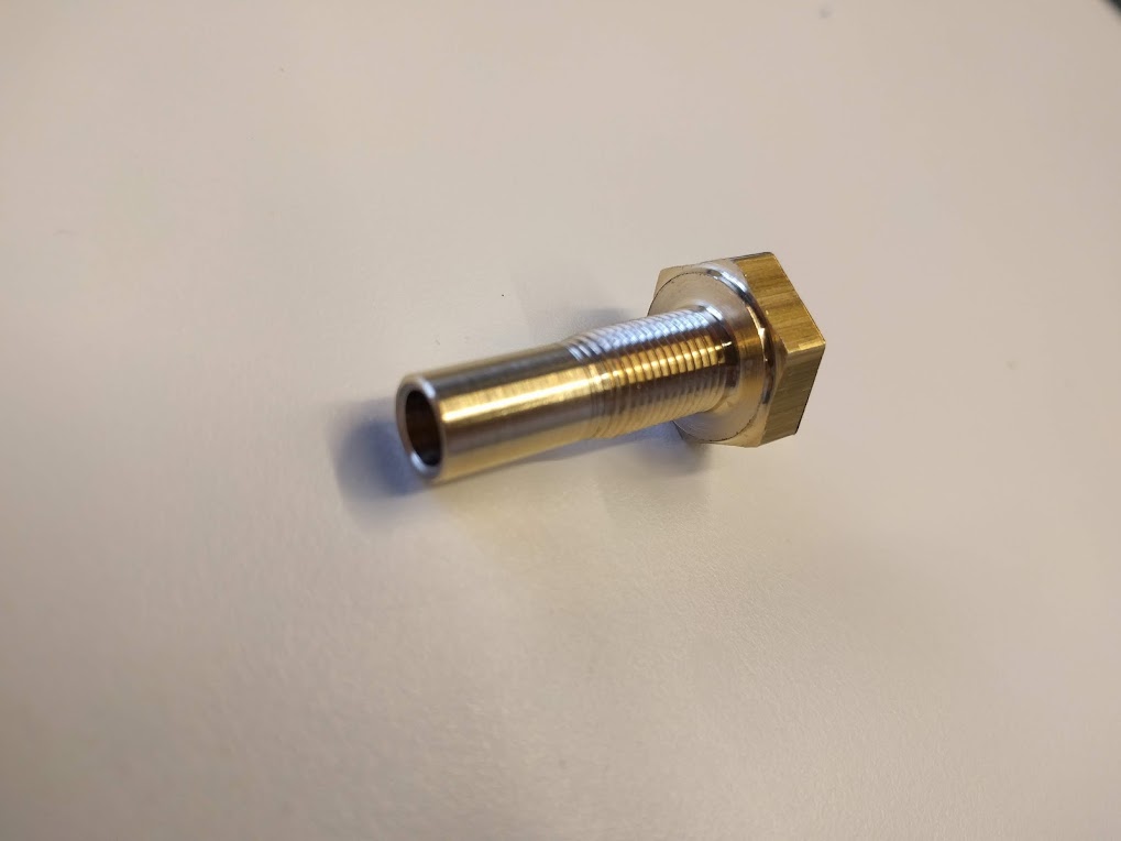
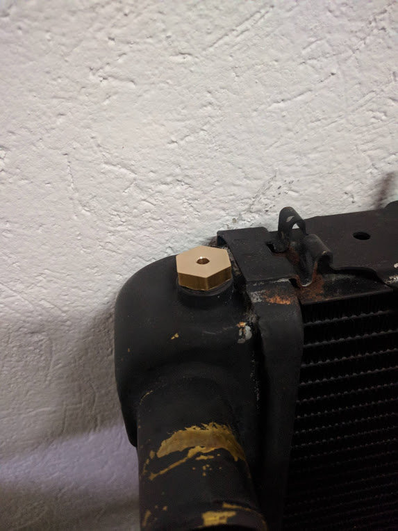
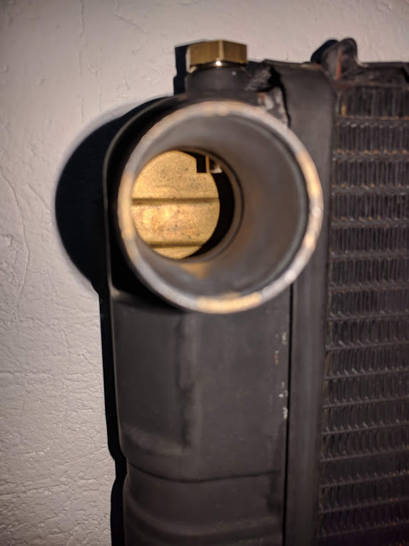
Have made first prototype of radiator bleed bolt where I plan to mount a thermo-switch for overheat warning scheme. Few sneak peek pictures below 
I have ordered suitable thermo-switches that I plan to mount into the bolt, but they will arrive only next year.
1 Like
I’m confused. Why don’t you just mount a sensor in the LH thermostat housing?
I already have a temperature sensor in left thermostat housing. What I want to have here is additional warning system that will warn the driver if engine is overheating.
I fitted a dual Engine Guard wth the thermistors bolted to the heads at the thermostat housings.so I now have on the dash a digital temp readout with an adjustable audible/led alarm.
I have had this for quite a while now and found it simple to install, cheap, reliable and useful.
Initially I found it under read by 6 C (bench test) In the 75-100 C range so I got the company to adjust it for me and now it’s fine. They were going to look into supplying them with a trim pot on the readout fo DIY calibration. Maybe they have now done that.
Trev
I have never seen a difference of more than 3-4 degrees between the two banks. Prior to install I checked the gauges with a thermometer and a pan of water on the stove. Running from cold to boiling a couple of times they tracked within 3-4 degrees of each other throughout. I am sure the banks are not identical, but in my car they don’t vary much.
That’s exactly what I did. Two AutoMeter temp & an oil pressure gauges where the trip computer/clock were, one sensor in each of the water rail’s.