Late 1988 XJ-SC with inoperative speedometer, trip computer and cruise control. This car is new to me, about 6 months. I recently joined the forum and I posted about trouble shooting an idle issue. Anyway, I’ve been driving the car some now. When I first got the car the speedometer worked. Didn’t have it on the freeway so I hadn’t checked the cruise and I didn’t really know about the trip computer. We did a bunch of maintenance to the car over the last few months (mainly changing hoses, fuel lines, spark plugs etc…). Now that the car is back together we started driving it. Initially the speedometer worked but the cruise didn’t. I believe the trip computer also worked when the speedo did. To trouble shoot the cruise we took the bellows and the actuator thing off the front, opened it up and cleaned the actuators/solenoids (they were sticky but now work when 12v is applied). However as the car was driven a bit more the speedometer would quit and then work again. This only happened a couple of times. Now it just doesn’t work as well at the trip computer and the cruise not working. After read what I could on the forums it sounds like the speed interface or the sensor on the diff is bad. I’ve check all the connections and they seem good. Everything looks to be in good condition, no corrosion. I do not see any broken or bare wires. I removed the interface unit, opened it and it all looks in good condition, however I can’t inspect the circuit board very well as I can’t get the circuit board out and I’m afraid of damaging it if I try too hard. I looked at the sensor through the access hole in the trunk. It appears undisturbed. Try as I might I could not find a good description on how I might test the sensor without taking it out of the car. And I’m a little afraid of removing the sensor as it seems a bit risky putting it back in and getting the spacing correct. I don’t want to end up breaking the sensor in the diff and then having to remove the diff. AND it seems the opinion on the forum is that those sensors don’t just go bad very often.
So my questions, 1 - are there any simple tests to check these components in the car, 2 - does it make more sense to just buy a new interface unit and see if that fixes it ~ $100 shipped, or 3 - should my next move be to remove the sensor to see if there is damage visible inside.
As usual I really appreciate any help/advice people have.
On the earlier versions (my car), with the sensor mounted at the transmission, cold joints inside the sensor is a common issue. Had the same problems and fixed it by resoldering the joints.
Only way to test the sensor it is to remove it and hook it on a oscilloscope.
On the basis it’s a simple two wire, hall effect sensor, you should be able to test it with a voltmeter.
Connect the meter and spin the sensor drive an it should create a voltage that rises with speed.
Hello Ryan - on my 1991 V12 Coupe, I experienced the same symptoms as you, where speedometer stopped working - I have purchased another instrument panel with supposedly a known working speedometer instrument (have not installed this yet), purchased a replacement used interface unit, and removed, cleaned the end of the sensor in the differential, and remounted the sensor - I was told by another member here that I should be able to see a 26 ohm reading for the sensor but did not get that reading - only read open - I did install the second interface unit but did not get the speedometer operational - I was told to check for 5vdc to 7vdc at the interface unit, on the wires coming from the instrument panel, and I did get 7vdc - so, bottom line, I have no results as to the problem yet - just writing to let you know areas of testing - I will be posting my results, when I get all working, here, and in another thread that I had started, asking for insight to fix - Tex.
Terry - I think my next move is to test for 5v to the sensor. I thought maybe I could put a volt meter on the signal wire from the sensor to the interface, put the car on stands and put it in gear and watch for a voltage change. Just tying to be sure I’m testing it correctly so I don’t ruin something that isn’t broken. Sensors seem hard to find and are quite expensive. I’ve found a used one on eBay for about $300 shipped. Too much to just buy it and see.
I had a speedo that was intermittent to useless, and after going into a well known XJ-S workshop it worked better but even then when I get to 50-60 it tends to lag and other times never reports that I’m at 70mph. I bought a digital display, reliant on GPS, in the end as it was taking too much time and effort.
If someone posts up the speedometer wiring diagram I’ll take a look at how it functions.
I am familiar with two wire, hall effect sensors feeding an interface and three wire digital sensors feeding directly to the speedometer.
Normally any electronic speedometer uses +12v and Gnd to power it, then there is a +5v trigger line fed from the speedometer, to the sensor.
When the +5v trigger is connected on/off to Gnd the speedometer sees this as a distance pulse. The more distance pulses per second, the faster it reads.
A three wire sensor also has +12v and Gnd to power it and creates the shunt to Gnd for the speedometer pulse wire on the third pin.
A two wire sensor creates an oscillating variable voltage, which on the basis there is an interface, is converted to digital On/off signal for the speedometer to use.
I found another post somewhere that someone indicated a way to decipher between a faulty interface unit and a faulty speed sensor was to drive at a constant speed, watch the Avg Speed setting on the trip computer and then push the reset button. If the Avg Speed showed a speed that was close to the speed you were traveling then it was likely an issue with the interface unit, and if the Avg Speed went to zero is was likely a faulty speed sensor. Does this make any sense? I did this and of course the Avg Speed went to zero as did all of the other mileage related info on the trip computer: mpg, trip distance, avg speed, etc.
Dieselman-
Is this the kind of diagram you’re looking for? Page 147 shows wiring for the speed sensor, interface, trip computer and speedometer for a 1988 XJS.
Exactly right, thanks.
The speed sensor is a two wire, hall effect sensor which generates a variable voltage and frequency signal. It is a small voltage generator.
The speed interface converts the analogue speed sensor signal into a digital signal (on/off) for the speedometer and trip computer to use.
It shunts the output pin to Gnd for each speed pulse.
The speedometer is a three wire device which sends a power signal (probably 5v)to the speed interface, which is shunted to Gnd by the speed interface to create pulses for the speedometer to see.
A speedometer can be tested by supplying it with +12v and Gnd, then shunting the signal wire to Gnd rapidly on/off.
A speed sensor can be tested using a voltmeter, or oscilloscope.
A voltmeter will see varying voltage, an oscilloscope will plot a trace of that.
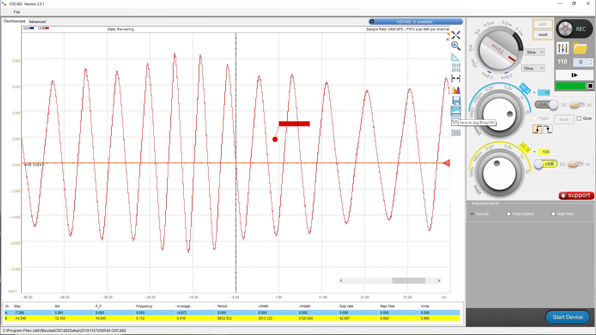
Oscilloscope trace of an analogue, two wire, hall effect sender.
Digital, three wire speed sender signal. The signal power is fed from the speedometer and is grounded by the sender. Note it is either on, or off, with stable voltage: the frequency varies for different speeds.
The above traces are from my own conversion from cable to electronic speedometer and I used the manufacturers speed interface and two wire Hall Effect sender, i.e. the same setup as your Jaguars.
Later cars went to a digital sender and do away with the speed interface.
First thing to check is power and grounds at the connectors for the trip computer and the speed interface box. Note that the instrument cluster, the speed interface and trip computer all get their power from the same fuse, and all get power on a green wire. If the rest of your instruments work, then the fuze is good. Pull the connectors from the trip computer and speed interface and test for power on the green wires. Also check for good grounds at the speed interface and trip computer on the respective black wires at the connectors, preferably with a test light to load the grounds.
If those check out ok, check for output of the speed sensor as dieselman suggested. If you have a signal there, check for output signals at the two speed interface outputs at the speed interface on the red and blues wires. Note that the wire colors change when they get to the speedo and trip computer. If you have power and ground at the speed interface, and a good input signal, but no output signal, your speed interface is the culprit.
Remember, the output signal voltage from the speed interface is actually supplied by the speedometer.
The speed interface shunts that signal to Gnd to create the pulses.
I’m a bit of a novice when it comes to electronics but I think I have a decent understanding of the basics. So let me know if my thought process makes sense or if I’m totally off base.
So I should be able to test for 12v to the speed interface by disconnecting the interface and testing for 12v from the green wire at the connection
I’m not sure which wire (the red or the blue) so could I then test for a voltage from one of those wires at the interface connection to the sensor?
Finally, if I know which wire sends power to the sensor could I then make a jumper wire for the wire with power between the interface and the sensor connector. Then use a voltmeter on the other wire to check for an intermittent voltage signal from the sensor as the wheels on the car are turned. Would this generate a voltage that I would be able to detect?
So a quick update. I disconnected the interface unit and checked for voltage at the green wire from the car. There is 12v from the green wire. I then reconnect the interface unit and then I disconnected the speed sensor from the interface unit. I then checked voltage from both the red and blue wire from the interface unit. There was no power to either of these wires coming the interface.
I did these checks with ignition turned on but with the car not running.
Firstly, try to perform checks with everything connected, as it puts the electrical system under load.
Speed interface.
Check there is a good +12v power feed on the Green wire (G)
Check the Gnd on the Black wire (B) is sound.
Speed sensor.
There will be no power coming out of the speed interface into the Red (R) and Blue (U) wires, as the speed sensor is a generator and sends voltage into the speed interface.
To test the speed sensor, connect a voltmeter, to the Red (R) and Blue (U) wires and spin the speed sensor.
You will see a voltage being generated.
For the speedometer to function it needs +12v on the Green wire (G), Gnd on the Black wire (B), which should make it output a voltage on the Blue wire (U)…Expect 5v.
To test the speedometer connect a flylead to the Blue wire (U) and with Ign switched on, rapidly make and break a Gnd connection, while watching the speedometer.
If the trip computer displays distance travelled, the speed sensor and interface are working, just the speedometer is not, conversely, if none are functional the issue will be something to do with the speed sensor, or interface unit…or lack of power/Gnd.
If you can’t obtain any reading from the speed sensor while connected, or make the speedometer respond, try disconnecting them in case the speed interface is shorting them out.
Further testing today. I think I was a bit confused and I think I have some good news. We put the car up on jack stands to test the speed sensor. With the car running and in gear I checked for voltage from the speed sensor. There was none. So then we removed the sensor from the diff. The sensor looks good inside. No obvious damage.
Here’s the good news. After reinstalling the speed sensor we tested it again. Car up, running, in gear. At first, still no voltage. Then it occurred to us, maybe we need to be checking AC voltage. All this time I have assumed we were looking for a DC current as that’s generally what I’m used to dealing with with car electronics. We switched to AC and what do you know, we got around 1.5 volts AC at idle and this rose to around 3 volts as we gave the car a bit of gas. So the good news is we think the speed sensor works.
With a presumed working speed sensor all signs point to the interface. I ordered a new one. In the mean time we decided to open the faulty interface unit. I was reluctant before to work too hard at taking it apart for fear of damaging it but now what’s to lose, it doesn’t work. We had to cut the little plastic box up to get the circuit board out. The circuits all look ok with no obvious burned out components or cracked solder joints. The only thing we could identify is possibly there were a couple of components that were too close together? Perhaps touching and shorting out? With some careful bending we straightened some things out and for shits and giggles decided to put it back in and test. Of course, it worked! The speedometer and trip computer are now working. After a short test drive we found that the cruise still doesn’t work. I suspect a leaky bellows but sticky solenoids may also be contributing.
Anyway, a new speed interface is on the way. Things I’ve learned are that the speed sensor needs to be tested for AC voltage. Thanks all of you that helped trouble shoot this problem.
The fact about the AC voltage test is very interesting.
Sounds like a typical cold joint problem at your interface unit.
Since it’s open you could solder all the joints.
Had the same problem but with the sensor, cold joints are not alway visible with a naked eye.
Apologies, I should have said a two wire sensor creates an AC voltage, it is just a single phase alternator.
A low wattage test lamp should have been able to illuminate with different speeds varying the brightness.
You can see the AC sine wave in the oscilloscope capture I posted earlier.
Here again.