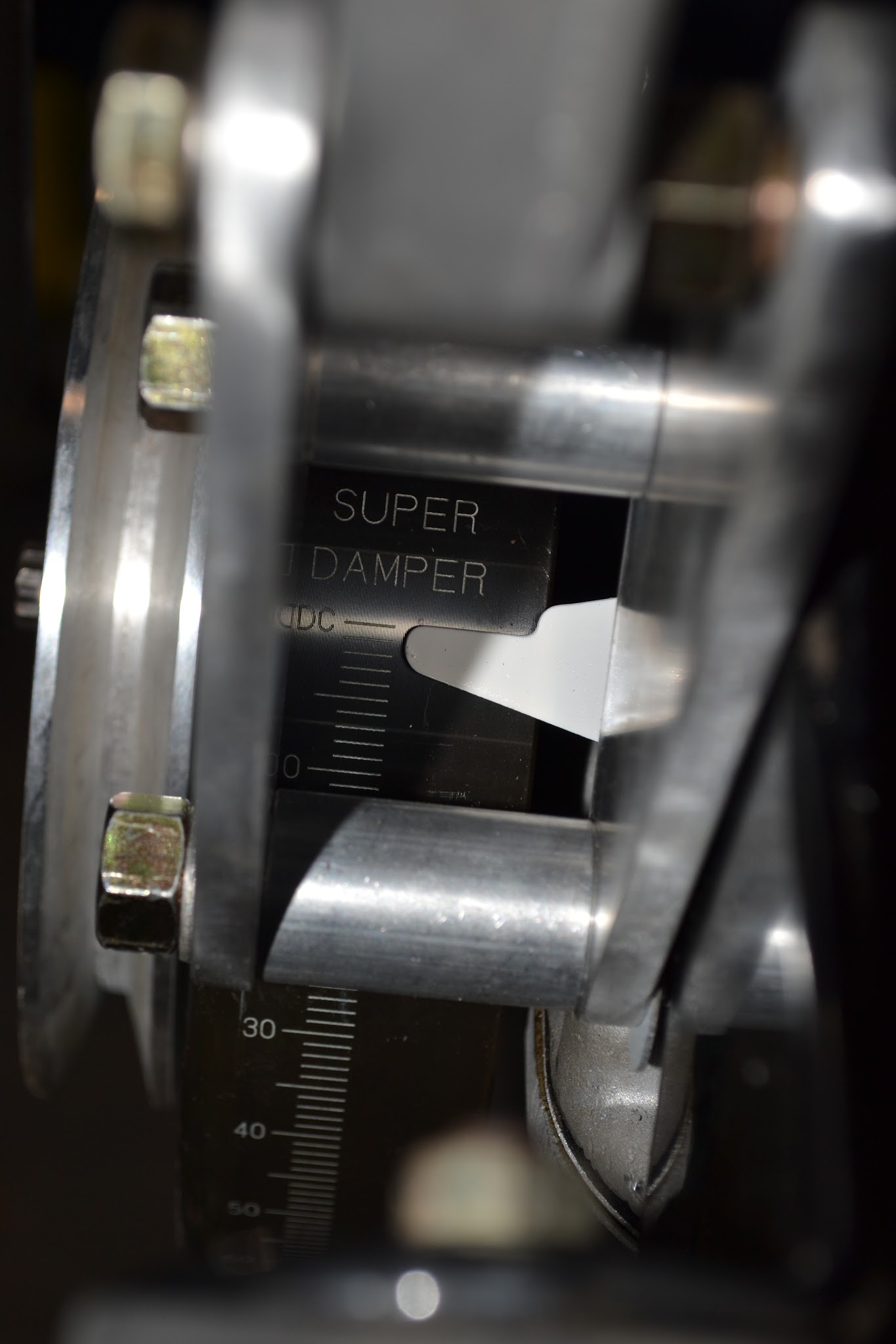
I wanted to confirm the timing on my 120. I located the timing mark on the crankshaft and lined this up with the mark on the inspection hole of the bellhousing however # 1 and # 6 pistons are at BDC?
With the timing light and engine running there is no sign of the timing mark.
Whats happened here?
Regards, Graham
Flywheel on 180 deg out?
Agree but wondered if it was possible as I assume the flywheel has dowels to locate it.
Robin’s probably right.
Doesn’t really matter. The only problem would be if you had the flywheel and crank balanced as a unit rather than separately.
Just find #1TDC using a dial gauge and rod in the spark plug hole and then put a new mark on your flywheel. Or just ignore the flywheel mark and use the one on the harmonic balancer.
Probably has, but engineers like symmetry so they would normally be at 180 deg as well ![]()
Robin is correct; your flywheel has 10 bolts and two dowels 180 degrees apart, so it is possible to put it on 180 degrees off.
It is possible to fix it in the car by supporting the engine under the rear of the sump and just pulling the gearbox. My preference would be to pull the engine and trans together.
If you don’t want to change it, you could set it at the arrow mark, then rotate it while carefully counting the teeth until you were 180 degrees rotated, then make another mark such as a few punched marks or something.
As I recall there are 132 teeth, so you would rotate it 66 teeth, and check that your pistons are now at TDC.
My 120 has the .Flywheel 180 out some DPO…and the flywheel mark thru inspection hole is BDC #6… The 120 did NOT have marks on the damper…tho they could have been added by anyone later…any such must be verified. So…take time to verify…and find TDC on # 6 on compression: #6 is…the front cyl…a little rubber stopper in the spark plug hole will pop out smartly on compression…(remove all spark plus to make rotation easier…either via damper/crank nut or roll car in 4th. Now.find exact TDC…I used a dial indicator…rubber hose on the end to extend it a bit. there is some “dwell”" a point at TDC where there “seems” to be no movement: …be sure it is on compression…Once found, now mark flywheel thru the porthole…mark the Damper. White nail polish or white paint …from that point…each tooth is 2.73D. Note you are now looking for teeth that show up BEFORE reaching your TDC mark.
Engine rotation is counterclock…best to rotate only in that direction…except small back and forth to find exact TDC…but final rotation should be the counterclock…this is…as viewed from driver position.(confused?..as from front of car…if looking at the damper…it is clockwise…aaarrrh ) .the fire order is 624153, The distr rotor rotation is counter clock as viewed from above. Then mark you desired static timing: . 5 deg: early XK120s per manual. (approx. 2 teeth, is 5.46 de, each tooth is 2.73 deg, (132 teeth, 360 deg)
or often 7 deg: generally for the later XK120 8-1. Both standard and SE. See SB 124 May 1953 …approx 2.5 or 3 teeth, and 3 teeth is 8.19d. Later cars or rebuilt distributors may like 10d-12d . 4 teeth=10.92
Fine tune with Vernier on distrib…(set initially with Vernier in middle…or dep on where you set initial set Vernier so you can adjust in the direction you think you will need to turn. My recommendation is Pt gap .016, spark plug BP5ES or BP6ES or equivalent…025 to .028. Do not need platinum…do not use Iridium.
Cheers Nick
I find it rather remarkable that the sight hole for the flywheel’s timing mark is on the side opposite the dizzy.
Ah, yes. I forgot. It’s British.
2 Likes
Thanks for the info.
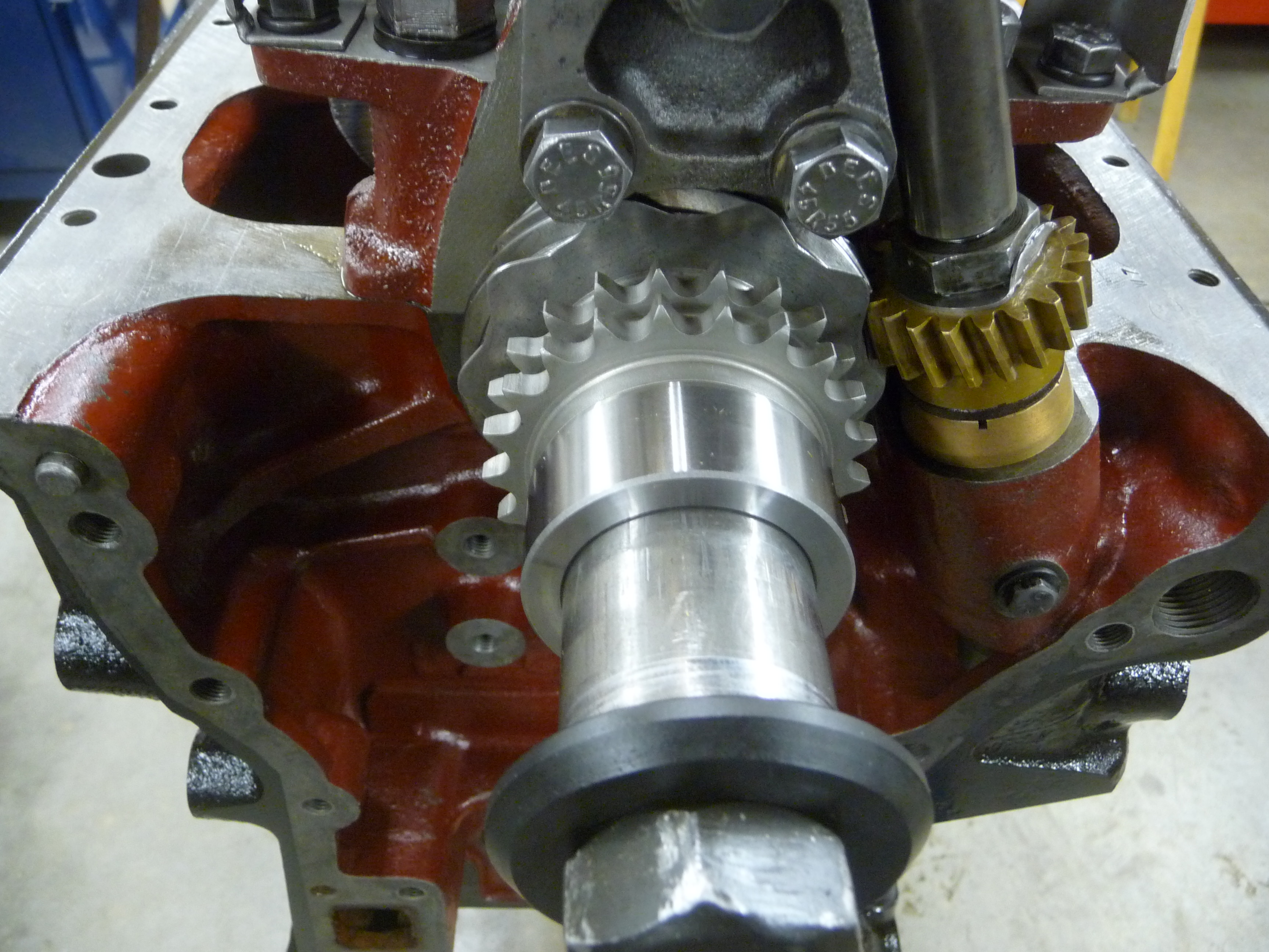
Is it acceptable workmanship that a professionally rebuild engine would not have had the timing marks line up and that it also has a front crankshaft oil seal leak shown?
Wouldn’t this be engine rebuild 101?
.

Not in my book. I would want them to fix the front seal.
Fitting “upgraded” teflon front seals is a bit of a fraught process and they do leak from time to time. Personally I have gone back to using normal nitrile rubber seals. They seem to be adequate for most modern automotive applications so they should work for the XK engine.
As I said the flywheel problem shouldn’t cause any real trouble. WRT getting TDC I personally don’t think counting flywheel teeth is accurate enough. You should do it properly with a dial indicator on #1 piston.
Piston dwell at the top of the stroke makes determining TDC directly an inexact problem. If you wish to identify the exact point of top dead center, the best method to use is to thread a positive piston stop into the spark plug hole on #1 or #6. Turn the engine by hand until the piston touches the stop. At that point, mark the flywheel or damper. Turn the engine backwards until the piston once again touches the stop and mark that spot. The exact TDC will bisect the two marks.
That’s how I was taught. The piston can hang at TDC while the crank can move. With a flywheel with a large diameter, the distance between the marks can be quite large while still being only a degree or two.
1 Like
Is #1 piston the one in the front or the one in the back?
Traditionally, #1 is the cylinder on the back of the engine: you can time it on #6, by paying attention to the cam angles.
1 Like
Graham:
As an experienced Jaguar rebuilder/restorer once said to me, “You are never going to stop all the oil leaks” (as we have joked many times on this Forum it was Sir William’s method of rust prevention). However, that being said the amount of oil loss you indicate appears excessive. One tip the aforementioned restorer gave me was to use the later (E-type) rope seal which has a wire through the centre. Also, make sure that the two front bolts effectively screened by the crankshaft damper are torqued up tight as they are either side of the lower seal (they can be accessed with an extension on your ratchet). When I had my damper rebuilt I found I had neglected these in my periodic check of the sump bolts. What had formerly been a sheen of oil sweat after a drive has now been virtually eliminated.
Chris.
#1 and #6 are both at TDC at the same time. The position of the camshafts determines if that is the compression stroke or the exhaust stroke. You can view the position of the exhaust cam lobe on #6 by removing the oil filler cap. If the #6 exhaust valve is open, it is on the exhaust stroke and #1 is on the compression, or firing, stroke, and vice versa. For the purpose of marking the damper or flywheel, it does not mater which.
2 Likes
I have read many responses over the years about the problems with rope seals and their “proper installation”. Some have claimed they knew how to do it and could produce a leak free result. That may be true but for how long? When you think about the design, it is a piece of soft graphite loaded rope that is initially compressed against a steel collar that mounted on the end of the crankshaft. It will eventually lose its compression and begin to leak. The same design is used on faucet stems, and most valves, but the the top nut can be tightened as the rope seal wears. There is no means to retighten the rope seal on the crank shaft. So they eventually leak.
I had mentioned, in another thread, adding a real lip seal to the front of the crankshaft to replace the original rope seal that is housed in the bottom of the timing cover and the top of the oil pan. The seal is available from all the usuals, has a metal outer casing and a spring loaded flexible lip seal that contacts the removable spacer located on the end of the crankshaft. Here are a couple of pictures of the seal sitting in the timing cover, shown upside down for clarity:


In order for it to fit properly, a bit of material was machined from the groove on the timing cover, the oil pan groove had adequate clearance. The seal is installed with a bed of silicone sealant around it as the timing cover is finally put in place. The clearance allows it to self center as the pan bolts are tightened up and the pan gasket is compressed.
Another leak path, that is not really obvious but must be addressed, is through the small clearance around the spacer that the seal rides on. This path needs to be sealed up by using silicone sealant on the inside of the collar as it is being installed, or by purchasing an upgraded collar that has an o’ring groove in it. I prefer the new collar, as most original collars are already worn out. The addition of an o’ring eliminates that oil leak path. See the following picture:
The end result is a leak free front timing cover.
“traditionally” for what auto manufacturer? Many have #1 at front…for Jauar #6 is at front and #6 is used as the tune reference in Factory Manuals. The piston stop method is fine…and accurate…with care…of piston top…and the domed Jaguar piston top should not matter…some piston stop tools I have had did not thread well…risk of spark plug hole thread damage. Similar can be done with dial indicator to the piston…make marks when moves at each side of the :dwell…the mid point is TDC. The view of cam love via oil fill cap is OK…risk of error…a rubber stop that blows smartly out of the spark plum hole is proof.it is on compression. All…work.
1 Like
I found this very interesting, as I’m on my second new crank front lip seal, which still leaks. May I ask which supplier you used for the spacer the seal rides on, and is the O-ring down against the crank surface between it and the sprocket? I’m not sure, but I think they used a lip seal without the metal outer casing, because they talked about having to be careful with the amount of silicone used to avoid it distorting… And were you using a cast alloy sump pan or a steel one?
Chris
The S3 XJ6 seal has a silicone coated body, not bare steel, Teflon lips, and the sleeve it rides on has an internal o-ring.