I don’t have this clip but it would be a logical necessity. Which means I need to make one. In general terms, the anti-vibration coil should be positioned close to the moving item, i.e the distributor.
The clip then should be somewhere close to the other end of the coil. The idea of the clip would be to prevent any oscillating motion extending back to the connection point to prevent this point fatiguing. So, without my being able to check my car, I think the clip would probably go on the rear carb stud, possibly the front lower stud.
I have a problem with mine in that it has suffered many ‘adjustments’ over the decades and is now quite hardened. I will have to anneal it and rebend it to an attractive shape.
Presuming the Mark V would be the same, my vacuum tube connects to the front side of the front carb. The clip is on the bolt in front of the breather, since the next two to the rear of the breather are occupied by clips for the float bowl overflow tubes.
Thank you Peter & Rob, I have made a sketch of the clip as shown in the above photo, measurements are in mm, divide the measurement by 25.4 to get decimal inches for those who work in imperial.
My carby vacuum offtake is on the front carby on the side closest to the radiator so I have attached the clip to the bottom stud securing the carby. The only problem with this is that I had to grind down a 5/16" ring spanner & shorten it to tighten the nut.
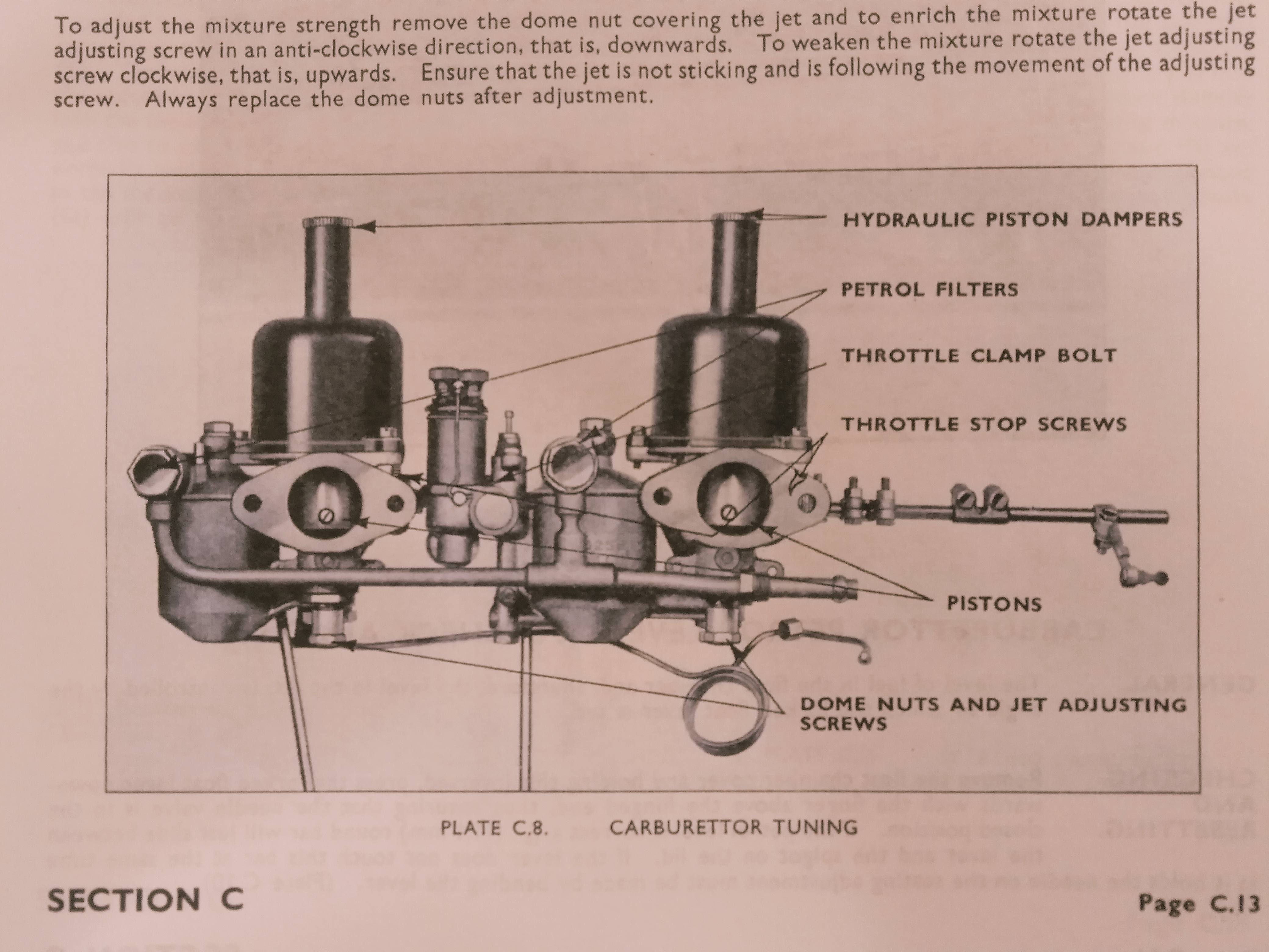
I checked the Mk V service manual and it shows a very good and clear picture of the side view of the carburettor assembly.
The vacuum tube runs horizontally under the carbs with the coiled section under the rear carb. Just visible, partly, is the clip. Its position looks like it would be attached to a stud under the front carb, so you are on the right track.
I seem to recall seeing a clip like this in one of my bits boxes and I had no idea what it was for. Now I just have to remember where it was.
PS, I took a photo of the picture noted above but I can’t see how I can attach it to this message. If I can work it out, I’ll send it on.
Thanks Robin, but the problem is I don’t have that icon on the mobile phone screen when in the Forum conversation, but I do on the computer - which, for some reason, refuses to turn on. Frustrating. I’m a lifetime member of the IHC club - I-Hate-Computers. On this screen I have the paperclip icon so I can attach it now.
Searching the archives I came across this image previously posted by Peter Scott, it shows the vacuum tube in a somewhat stylised & with a bit of artistic licence perhaps image. I have often wondered how photo type images in old workshop manuals are done because they don’t look quite real.
Very interesting, it shows the vacuum tube with a horizontal coil.
That image is from the Mark V XK120 sales brochure, and has been touched up probably by the air brush technique, similarly to the Service Manual and Handbook photos.
Hard to guess why the artist made the aluminum parts and fan belt tan color.
But the engine is actually that of a '48 Mark IV. No water pump extension, the damper is in front of the pulley, no generator mounting extensions, black tappet cover rather than aluminum, vacuum rather than manual advance, and a JH or SH gearbox rather than a double helical.
They were airbrushed on top of a black & white photo print. In the days before digital retouching basically all marketing material was airbrushed by an artist. My brother used to practise that as well. I am a digital artist myself.
I do like the airbrush look.
BTW none of those clips left in my car and engine, so it is good to know about them.
But in that photo / illustration it looks as if the coil in the vacuum pipe would be right below the rear carb and too high to have a clip on one of the tappet cover bolts?
FWIW my vacuum pipe had been pulled straignt by someone in the past. I broke it at the dizzy end and bought a replacement from SNGB and it is much shorter. So short that I could not make a coil like that, but it’s there in the car now between the front carb and the dizzy.
That’s funny, as I have a LHD MKIV engine from ca. July 1948 in my MKV DHC #647194, and I thought that was all as it should be.
Also good to note that as seen that engine could only have been used in an RHD car as the oil filter needed to be relocated on LHD MKIV’s due to the steering column etc.
But in a MKV that would be ok, the waterpump, the generator and the harmonic damper were moved forward but even in the Jaguar handbooks there are many photos of similar MKIV engines in MKV’s.
Maybe they made the changes only after they had started to assemble the first LHD MKV’s???
I don’t understand why it needs a coil. Am I not right in saying that the manual advance control was dropped when the vacuum advance was fitted and thus the distributor shouldn’t be moving relative to the rest of the engine.
I think you are right, it should only move in relation to the engine when timing is set. Maybe to help prevent hardening and cracks due to vibration? I have also seen coils in older SU setups with copper fuel pipes.
I am not worried about the coil, neither the missing clips, only interested, one more thing to look for.
Yes, a coil in the tube would not be absolutely necessary, though you need some amount of extra length with a bend in it for easy installation and adjustment.
The vacuum advance began with the P engines and S1502.
Possibly as this was their first use of vacuum tubes, their supplier sent them something he was making for other customers, and Jaguar chose to make a coil as a way of stowing away the excess length. The tube on my Mark V is shorter and I can only get one loop in it, so perhaps on their next order they had the supplier make shorter tubes to save sixpence.
Or Mr. Heynes was remembering his pipeline design training from engineering school, and thought it should have an expansion loop because of vibration. Expansion loops are very common in long pipelines.
The clip is fairly long so I can tuck the tube up high.
I would say the clip at the forward end is a good idea, and probably essential, because it eliminates strain at the offtake connector nut when you are manipulating the distributor end. I’ll be making one for mine. Later technology would just have a short spigot at each end and a rubber tube between.
I’ve been thinking about that for a few days. The coiled copper pipe must give some movement if you want to advance or retard the timing by moving the body of the distributor. It also appears that the MKIV doesn’t have a vacuum advance nor an ‘Advance / Retard’ adjustment on the steering wheel manette. No doubt a time of transition.
Mild panic after reading these posts. My car doesn’t have vacuum advance- the advance mechanism is inside the distributor and is correct and standard according to workshop manual - engine S03xx