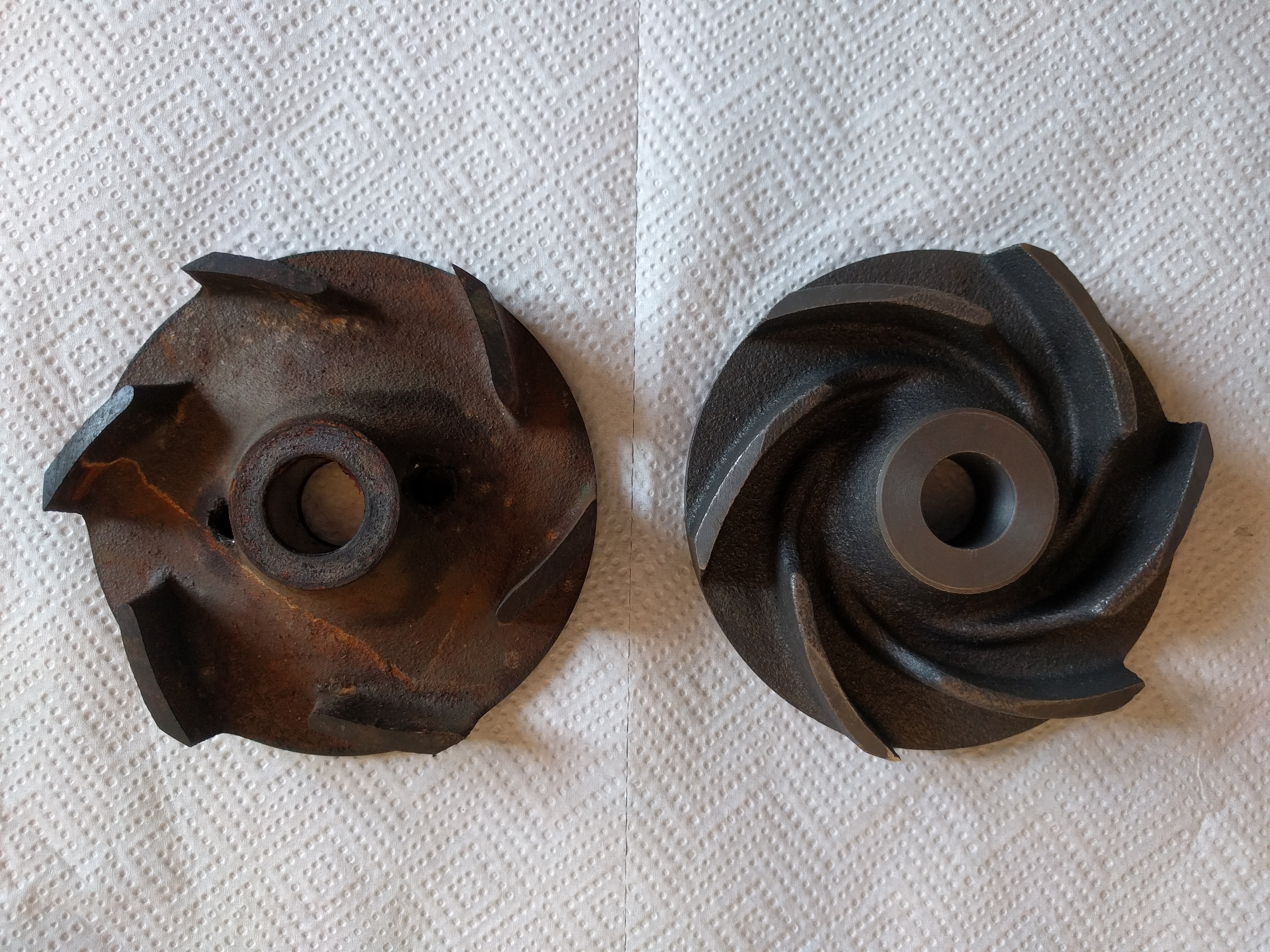
I had a spare water pump and decided to rebuild it and keep as a spare. Ordered a rebuild kit which included new impeller. Here’s a picture of my old impeller (left) next to new impeller from the rebuild kit (right):
Hi Jonas, I have one of the newer ones, not yet installed. I haven’t gotten to the water pump yet. I was looking at coatings which would improve pump efficiency and had some discussions with a company “Belonza” that were promising. Since I haven’t taken the original out, I didn’t know that it was different from the replacement. IMHO the newer should provide more flow at lower RPM. The one in my photograph does not have a locking setscrew.
The one on the left is the original style. The one on the right is the current replacement style. Both press fit. The early bearings had a hole in the side that accepted a tapered allen screw. Only problem was the hole was drilled through into the inside of the bearing. The later bearings are sealed. We have a setup that cuts a notch in the side housing of the bearing to accept a allen lock screw. Jaguar stopped using a lock screw in the early 90’s and relied on the press fit to hold in place. Either impeller are more than adequate for water flow.
My new bearing has a notch on the side and a new set screw so should be a direct fit. I was just thinking maybe new style impeller will have higher flow rate at idle. Probably quite difficult to test it though…
Kirbert
(Author of the Book, former owner of an '83 XJ-S H.E.)
8
With centrifugal impellers, the key factors are the OD, the vane angle, and the depth of the vanes at the outer edge. Just based on the photos, I’d say all three factors are the same for these two impellers. Differences at the ID end of the vanes makes little difference.
I broke my impeller trying to get it off, so I went to a junkyard and looked over the selection of Chevy water pumps. I selected one from a big block Olds or some such that fit but looked completely different, the vanes were only slightly backward-leaning while the Jag vanes are strongly backward-leaning. They looked kinda like the one in this pic:
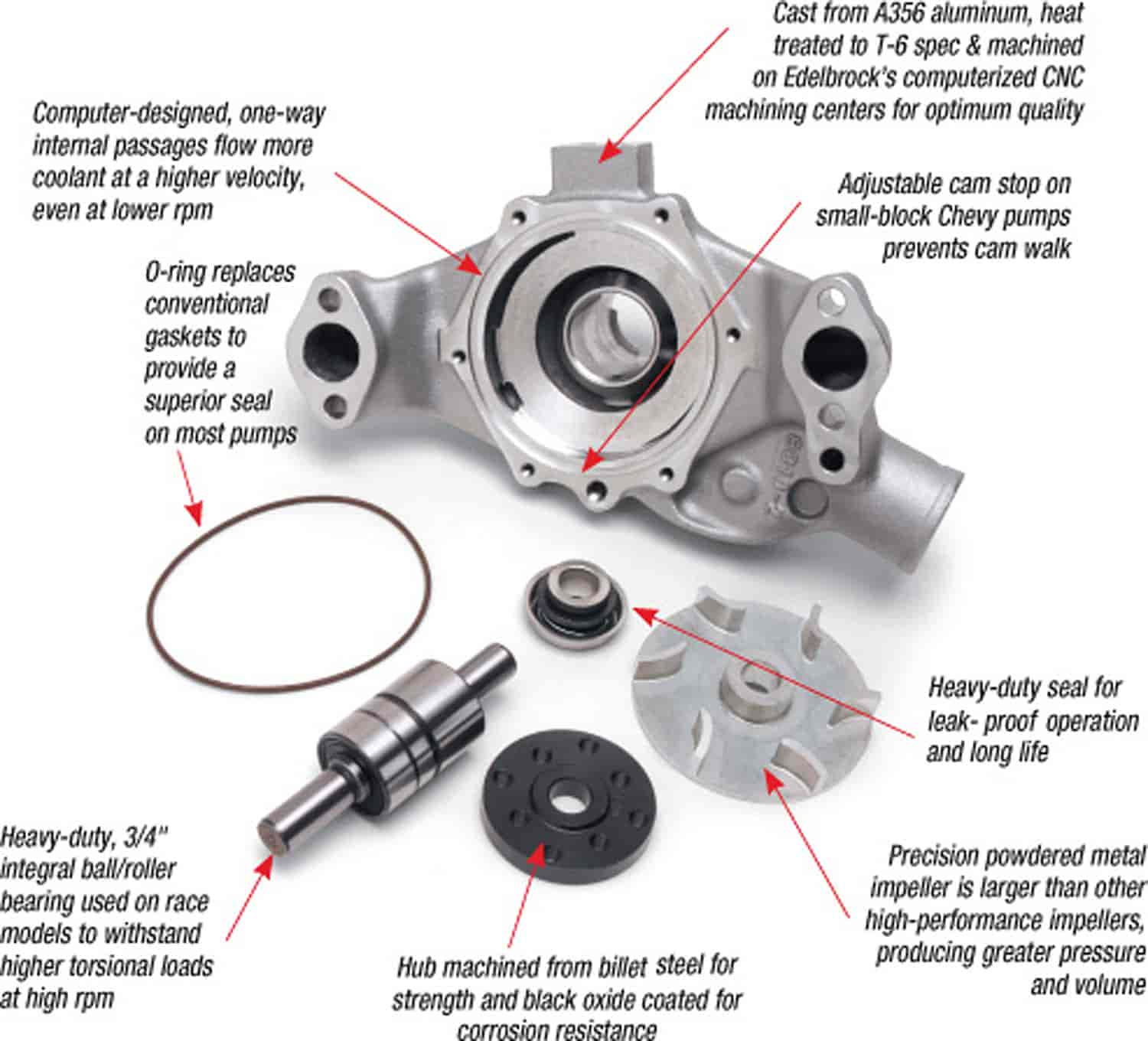
Presuming that Chevy knew more about keeping engines cool than Jaguar, I installed it and it worked well. However, looking online at the assortment of Chevy water pump parts available today, it seems apparent that most of them look very similar to the Jag part! Simple fact is, they may be the Jag part, meaning Jaguar may be simply using a Chevy part rather than making its own. Here’s a pic of a typical impeller:
It’s also worth noting that many Chevys and other cars use impellers that are stamped out of sheet metal rather than cast iron. The sheet metal is usually stainless steel, so while they may look cheap they are most certainly more corrosion resistant than the cast items.
Doesn’t explain all of the extra metal used in the cast. Why have the gradual ramp up, where there was none before. I defer the the pump efficiency folks to step in, I know my expertise in this area is limited.
Kirbert
(Author of the Book, former owner of an '83 XJ-S H.E.)
12
The additional lead-ins on the impeller vanes might reduce cavitation. That’d be about the only thing you’d expect such a change to help. Cavitation shouldn’t really be an issue if the system is properly pressurized and not overheating (!).
Hard to see in the first picture but both impellers are tapered on the vanes as the pump casting is concave.
Kirbert
(Author of the Book, former owner of an '83 XJ-S H.E.)
14
Yes, they must match the curvature of the pump housing. But even the Chevy impeller I used matched, so I’m guessing the curvature is fairly standardized – and again, Jaguar probably used the Chevy design.
Kirbert
(Author of the Book, former owner of an '83 XJ-S H.E.)
15
The original impeller has two threaded holes for using a puller, right? Does the new impeller not have those holes?
I have yet to see an impeller that does not either break or strip out the threads when trying to remove using the holes. The replacement does not have the holes.
I know very little about this, except that this area of fluid dynamics is one where there have been a lot of advances over the years. Which makes me think the old one both looks crude and will be crude, simply because the understanding of the day was very limited. The later one looks more “refined” which you would hope would be the result of someone doing their due diligence and actually simulating the thing with CAD. Dare I say there is nothing very comforting about the Jag cooling arrangement, with wildly different passage sizes and weird looking “artifacts” all over the place. But maybe it is just not that critical.
There is an interesting publication by Ford which details the development of the GT40 (modern) engine. In this, they paid considerable attention to the cooling arrangement and achieved extremely uniform cooling across all areas of the engine. Something that is probably lacking with the older engines designs. Can’t recall, but they might have used an electric water pump for that one.
A number of Jag enthusiasts have had good success using one (or two) electric pumps and ditching the old arrangement.
Just to add the the Ford story, it’s reported that they spent a considerable amount of time and money just on the Mustang GT 350 clutch development alone.
Unfortunately Jaguar never had the resources that the big car companies had and I believe that this is part of the reason that the early Jaguar cars have so many idiosyncrasies (Smile)