I am re- wiring my ignition amplifier…and cannot select proper wire from the ECU. What is color code of proper wire ?
Thanks, Sloth
Model year would be helpful.
a few wires either come from the distributor pickup coil, or go to the ignition coil. Those are easy to see.
The other two wires that go towards the back of the engine, one is for tach, and one is for ECU. The one for tach I believe has a cylinder shaped connector. The one to the ECU has a blade connector.
My XJS Service Manual Volume 4, page 86A-85 shows the tach wire AND the ECU wire color as W/S. (white/slate). Yes…both the same color. And you are correct 1) tach wire has the round male connector. 2) ECU has the blade connector. And for the other lookers…clicking on your Wayfarer icon shows this is likely your 1988 V12. SD Faircloth
Really? Either Jaguar changed that or someone modified it on your car. On my '83, both the tach and ECU wires were bullet connectors, but one was male and one female.
Ha! You’re right, I modified it! Done so many on this car, I forget what I’ve done.
Hi Kirbert:
My Jag is a early 89 xjs …previous owner or mechanic chopped any fastening devices and left naked ends…I guess I could make temporary connections until I have success…
Thanks, Ivan
Ivan,
Do you have copies of the Jaguar XJ-S Repair Operations Manual (ROM) and S57 Electrical Guide for your Model Year?
I have been successful at rebuilding several electrical harness while they were still in our Jaguars and also on my work bench after I removed them. I like to solder the repairs and cover them with shrink tubing and wrap them with high temperature vinyl electrical tape afterwards. I can’t imagine trying to do thsee repairs without the ROM and S57 on hand. I could probably do it with the ROM alone but would need a big magnifying glass and a beer or two to trace those ROM wiring diagrams.

Paul
I had a full injector loom made professionally using a loom machine. Just like OEM. I had some problems so I removed it and did some continuity tests. I found it had been made back the front, the ECU was talking to the A bank thinking it was the B and vis versa.
When I pointed this out to the embarrassed manufacturer he got back to me later saying he had done nine of them.
I think the only problem would be those with oxygen sensors.
Trev,
When I rebuilt the EFI harness in my wife’s 1990 XJ-S convertible (5.3L V12 with Marelli ignition) a few years ago I placed the harness on my long shop work table and measured, cut, soldered, shrink wrapped, and eventually wrapped with vinyl tape, each wire one at a time. I replaced a bunch of the old broken plastic connectors with new ones and made sure to test each wire from end to end before and after the repair. It was a lot of detailed work but very satisfying when the engine ran again for the first time. I learned a lot about the EFI system in the process by having to trace the wires and learn about all the sensors along the way. I can now look into that V12 engine bay knowing much more about how everything works together.
Paul
I wholly agree Paul. I obviously didn’t go to the trouble you did but in sorting out the juxtaposed wiring and everything else during the rebuild I found it became a cathartic process. A lot of swearing but in the end a lot of satisfaction. And like you I fine much of the mystery has disappeared.
Trev
Pin 18 will be the ignition signal connection on all 6CU and 16CU EFI ECUs with Lucas or Marelli ignition. The wire is always shielded, and usually white or white/slate, and it’s the negative side trigger to the coil, or in the case of the Marelli ignition ecu, a copy of it.
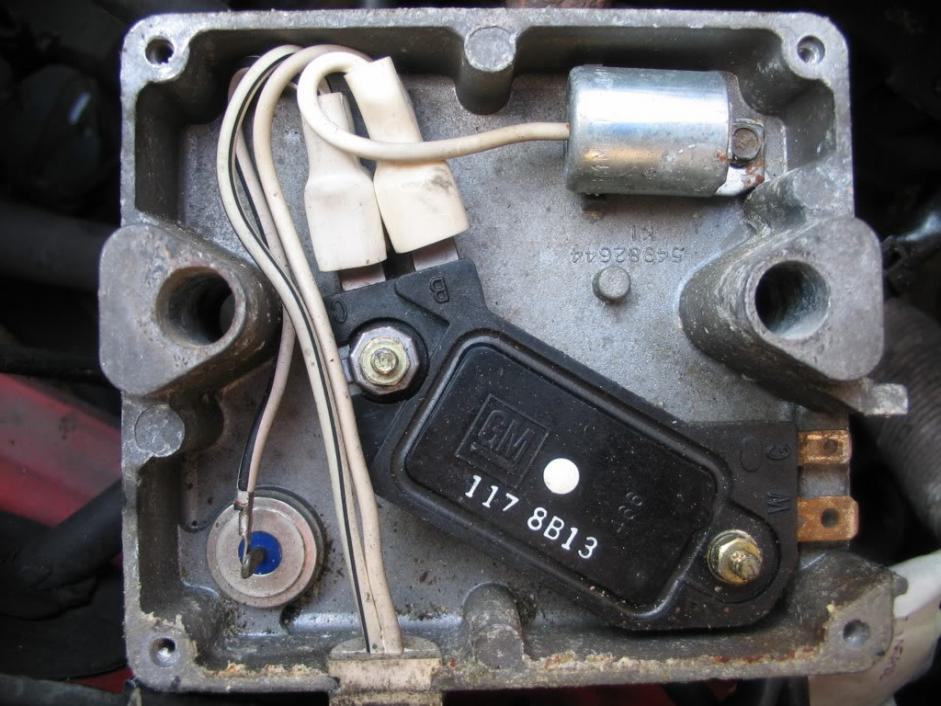
On the Lucas Amp, it comes from the 3 way split on the negative side of the output of the GM HEI module. Internally that’s “C” terminal on the 4pin GM HEI amp (one side is control / 2 pin trigger --> the other side is output +12V and switched ground or “C”).
Different variations on the same amp have different number of wires coming out of it, from two to 5 (one positive & one to 3 negatives - some with resistors in-line). There’s often-usually a 6.8kOhm resistor in-line on the split to the ECU pin 18.
It’s easy enough to crack the case on the amp and have a visual look if you’re unsure.
Paul K.
Hi Kirbert: '89 (early) xjs coupe
I am getting fed up with amp. replacement business. I just took delivery of two ignition amps. one was said to be new and never installed (it seems to look accurate) the other used as a test unit for shop use. ( I tried both and spark still weak). I installed a routine coil (average strength) and feel this may be my problem.
I am bringing this request to you, where is ignition ballast located ? Could this also be my problem ? I appreciate your help…
Ivan Pittsburgh, Pa
You could have one or more bad coils, or coils that are breaking down under high-heat conditions. The Lucas CEI system is an adaptation on the GM HEI module, and requires no ballast resistor to adjust charging. The electronics in the HEI module do that -controlling dwell/charging time. Because of this it allowed lower resistance coils to be used for faster charging. The recommended update, in fact, is to go to the more modern Jaguar very low resistance single coil DAC 6093 instead of replacing the old two coil system if a coil needs to be replaced.
The coil resistance is in “The Book” I believe (as well as in the service manual) but I’ve found they can still be failing even when resistance - at least cold - tests ok.
~Paul K.
Amp & amp failures: As you can see from the prior post, the inside of the AB14 amp is quite simple. It has a quality 4pin GM HEI module. It’s best to replace that (if known to be going bad) with a performance version, because the cheap cheapo GM 350 version is known to have a problem passing enough amperage to the coil(s) above 4000 rpm. That said, a decent performance module should suffice. It’s also a good idea to check the suppression capacitor / condenser to make sure it hasn’t failed internally and is shorting to ground. Just test for any continuity from wire to case. You may see it initially, but it should with a flash go to infinite Ohms. If it’s shorted in any way it needs to be replaced (any points condenser will do) or cut out of the system.
Reprinted from another post -CEI Ignition tests-:
The test assumes a fully charged battery
-
Measure voltage at coil “+” terminal with key “on”. It should be within
one volt of battery voltage. If not suspect a problem with the wiring to the
ignition switch, or the switch itself. -
Measure voltage at the coil “-” terminal. Result should be the same as at
the “+” terminal. If Ok, go to step 3. If not…
Disconnect the wire from the amplifier from the “-” post of the coil and
measure voltage again. Less than 2 volts means the coil is faulty. More than
2 volts means the amplifier is faulty. -
Disconnect distributor pickup coil from the amplifier (this is the
harness from the distributor that plugs into the amp). Measure resistance
across the terminals. It should be 2.2k to 4.8k ohms. If Ok, go to step 4.
If not, replace the pickup. -
Reconnect the pickup to the amplifier. Measure voltage at coil “-” post
while cranking engine. The voltage should drop. If OK, go to step 5. If
not, the amplifier is faulty. -
Check distributor cap and wires, distributor rotor arm, spark plugs, coil
wire
~Paul K
2 Likes