I have removed the manette from my 120 and there are some pieces missing so I am struggling with the finer details of construction although I understand well enough how the indicators should work and self cancel.
I have been looking at a previous thread:
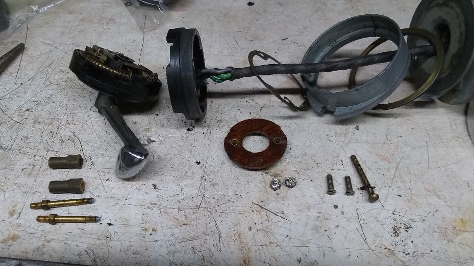
I have a some specific questions. Looking at this picture which Rob Reilly uploaded…
1/ There is a brass washer at the back of the Bakelight housing what is the purpose of this please?
2/ There is another brass washer between the self cancelling ring and the back plate in the top RH corner, I suspect this one is a bush between the stationary part and the rotating self cancelling ring?
3/ What holds the self cancelling ring on? I can see that it rotates with the large disc at the back thanks to the fingers protruding from this ring, but what stops it moving backwards and forwards slightly?
4/ The grub screws in the steering wheel seem to hold the large disc (with protruding finger) so that it rotates with the wheel. What prevents the centre part from rotating?
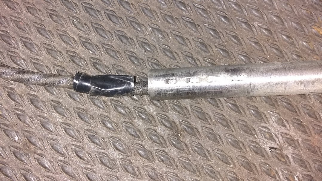
In response to number 4, the tube that is about 8” long attached to the manette, has small bumps along the shaft. These slide into a slot on the stator tube which is inside the steering column and fixed by a clamp at the front of the steering box. As the wiring is fed back down the stator tube (hopefully while someone pulls them through via the string previously recommended), you will feel the bumps engage the slots. Slide the manette all the way till it stops. Silicone lubricant on the tube helps. As the in and out is adjusted, the steering wheel moves in and out in this slot. Adjustment of the orientation of the horn/turn signal can be done by loosening the clamp on the stator tube.
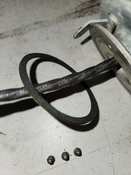
Notice the tape, this is a wear point on the wires as the wheel is moved in and out and the wires are rubbed on the sharp edge of the stator tube, an engineering design defect. Mine would blow fuses when I signaled a left turn. I wrapped tape as a temporary fix, and later substituted with shrink tubing.
slot on inner stator shaft
brass contact disc, the plastic push clips to this
Brilliant thanks Rob that’s really useful. How many wires do you have please, is it 4? If so I’m guessing the brass front washer with the electrical tab provides the earth for the horn? I am missing this but have 5 wires so I’m thinking someone has run an earth back down the stator tube.
The other thing, I still can’t see how the self cancelling ring which fits around the Bakelite housing doesn’t move backwards and forwards. What holds this against the back plate (where the screws go through to the Bakelite)?
I have bits missing and have haven’t seen a complete one assembled!
In Robs 6th picture it shows the cancelling ring and circular spring
This area is also where the L/R indicator brass contacts touch and allow current to flow
I have some Mannettes, and two of them have the fault that one of the indicator circuits has no continuity
I dismantled one, repaired wiring and re-assembled it, but the fault was still present
It appears one of the the inner brass contacts is the likely culprit, so I would have to dismantle it again to make it operational, not an especially pleasant thought
Thanks Tony. The bit I meant was this ring here which fits around the outside of the Bakelite switch module. I don’t quite see what stops this moving forwards in the direction of the bottom arrow…
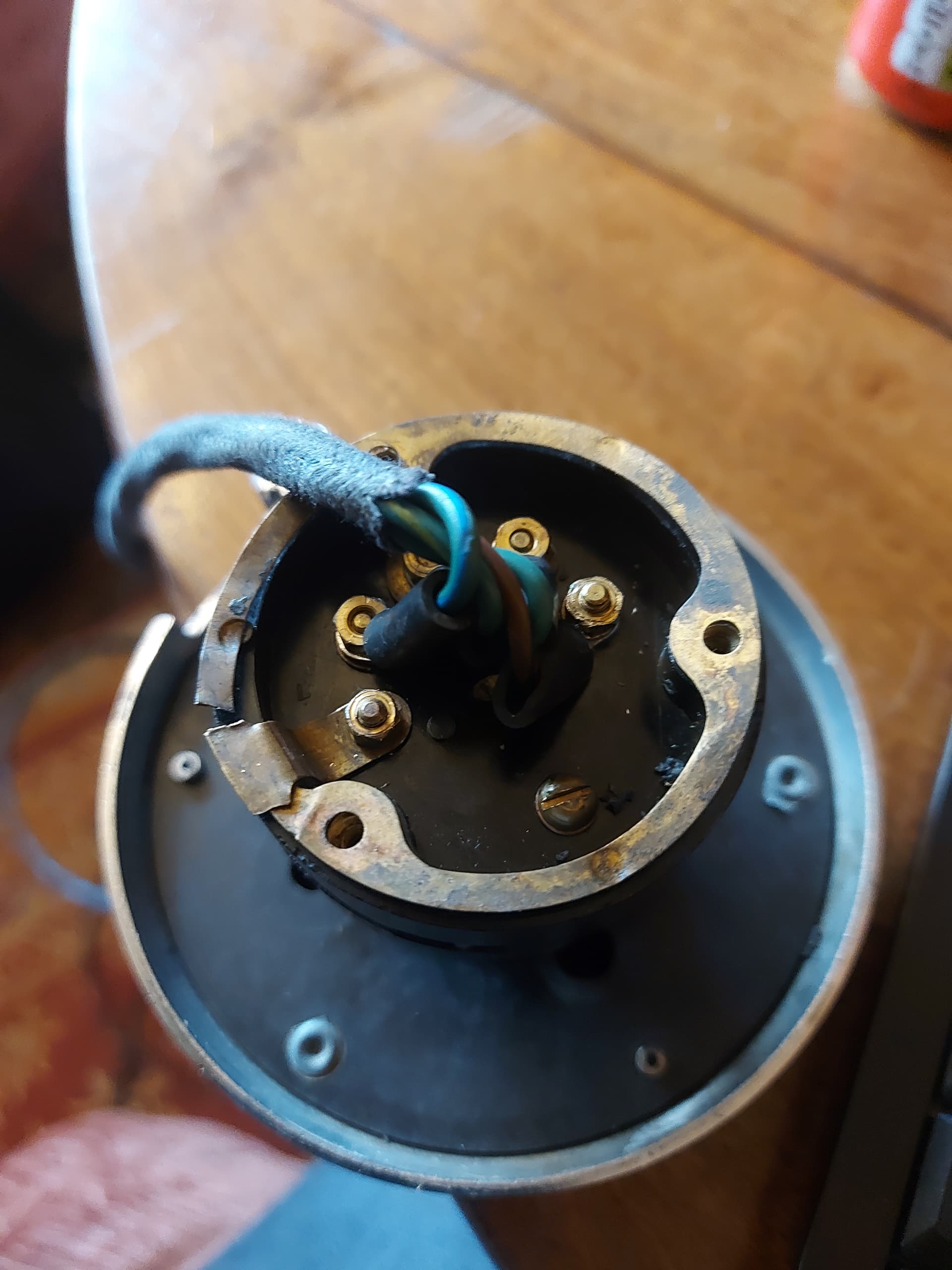
Thus the color scheme does not match the wiring diagram, so light green is right turn and connects to the green/yellow wire, dark green is left turn and connects to the green/blue wire, medium green is common and connects to the green wire, and purple is horn and connects to the brown/black wire.
This is obviously meant to be reset in the same sort of way because it has the two cancelling pawls protruding from the Bakelite. I do note it has a step on the front of the housing though so perhaps the cancelling ring (which I’m missing) was different on this one.
Not being an expert these seems to me 54 production date. It was positive earthed, meaning that the claxon was wired to the ground directly, simple modification to adapt.
This post was great. I bought a new manette and was having difficulty getting it into the stator tube. I’m not real familiar with these cars as I inherited this one. The previous manette had the 8" tube cut off by someone and wasn’t wired. Lew3 great idea to lube the tube and thanks for the heads up on the bumps along the shaft, and the picture from Rob actually let me understand what the slotted inner tube was. I used the idea of protecting the wire with shrink wrap at the end of the tube. Great information guys!