Hello All,
Crown Wheel and Pinion gear sets are lapped after heat treatment and supplied as a matching set.
On the small end of the Pinion Gear, there are various numbers, with one set relating to an offset, plus or minus, to the theoretically correct dimension “B” (66.67mm) shown in the following picture.
This dimension is a constant for all the common ratios, except 2.88:1 it seems.
The result of my measurement is 72.63mm for dimension “B” for the 2.88:1 pinion shaft, but this measurement includes all accumulated tolerances of bearing and differential case, therefore, is likely not the theoretically correct dimension from Crown Wheel Centre Line to ground face of the 2.88 Pinion Shaft.
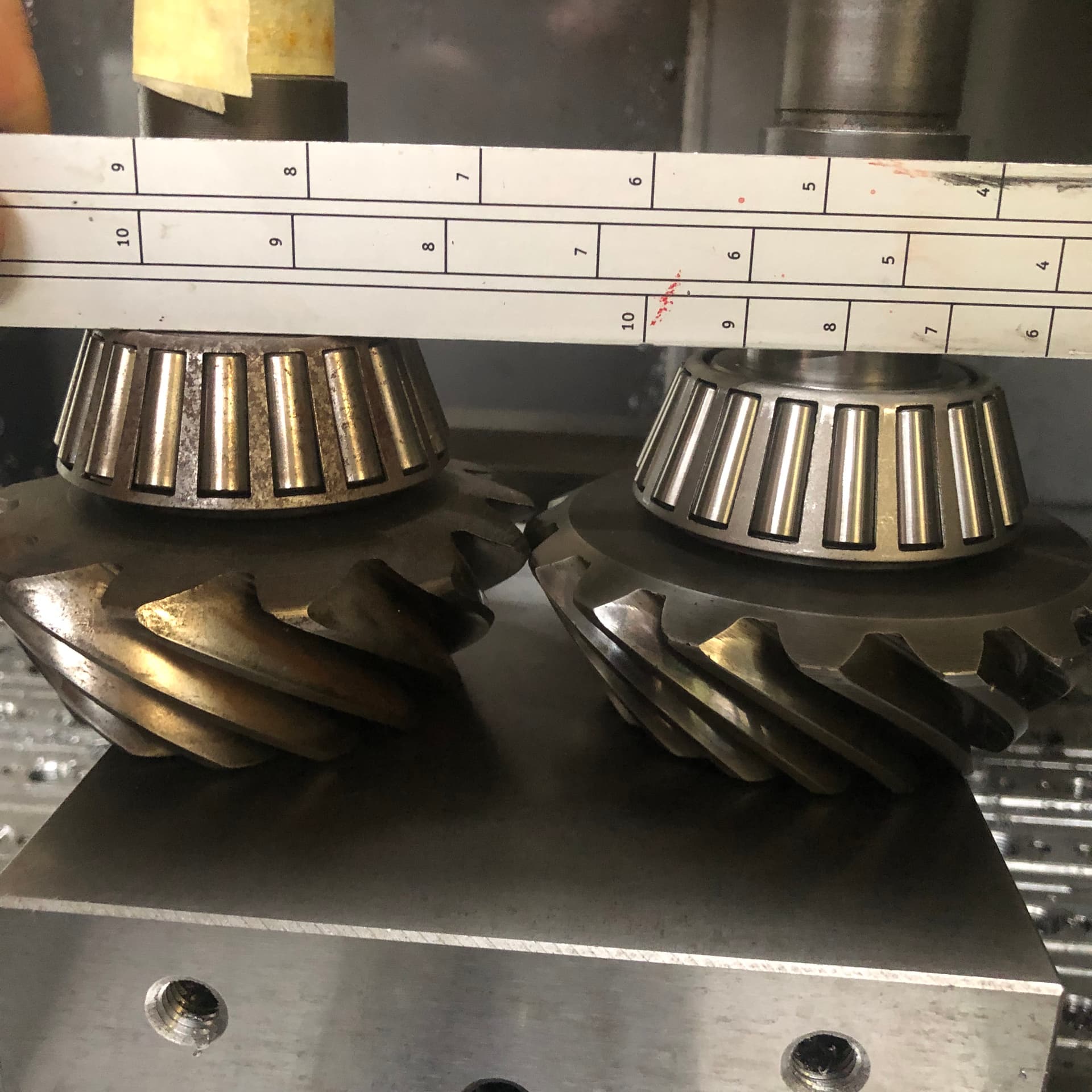
The difference is in the Pinion Shaft from where the inner bearing seats and the ground end of the shaft. This can be seen in the following picture, which is a comparison with a 3.31 Pinion Shaft on the left in the picture.
I haven’t been able to find what dimension “B” should be for a 2.88 Pinion. The manuals I have to hand simply states to set the Special Setting dial indicator tool to the setting block, but doesn’t detail its dimension.
My question, therefore, does anyone have the detail of dimension “B” for a 2.88:1 ratio Pinion?
If anyone on this board knows this dimension I’m betting it will be @Dick_Maury who has done many 2.88 gear swaps. I’m sure Dick will chime in when he sees this post.
Hi Bill I’ve been talking to a friend who is somewhat familiar with these 2:88’s. He asks me if your diff is a Salisbury or a Dana. He’s worked on the former, and might have the info, but he’s not sure if the info applies to a Dana.
My friends initial reaction to this is that he thinks the distance is the same 2.625 because the ring gear is different and that compensates for different (squashed) size of the pinion gear.
I can assure your friend that its not. If you look at the picture of the two Pinion Shafts in my opening Post, you can see, given that the bearing for the 3.31 and the 2.88 are the same, that the dimension from where the bearing seats to the end face of the Pinion gear is smaller in the 2.88 shaft (on the right in the picture). Accordingly, when assembled in the Diff housing, the measurement from the Centre Line of the Crown Wheel to the ground end face of the Pinion Shaft must be greater. 2.625" equals 66.67mm, my measurement of this dimension (dimension “B” shown in the extract from the Jag Manual) is 72.63mm.
This measurement of 72.63mm was made with no shims under the bearing cup and would include the manufacturing tolerances of both the Diff Housing and the Pinion Shaft and therefore is highly unlikely to be the true, theoretical constant used in the calculations for the shim stack required under the bearing cup. The difference between my measurement and the constant of 66.67mm (2.625") is very close to 6mm (just short of 1/4"). To bring the dimension to the 66.67mm (plus or minus the offset amount) would require circa 6mm of shim, which would have circa 6mm of the bearing cup sticking out of its bore in the diff housing.
Hi Bill, just seeing this post. I did not receive anything that I can find. As far as the gear height, the ring gears are different heights depending on gear ratio. The carriers are different heights where the ring gear bolts on to compensate for the gear height. When someone wanted a gear change, it was generally easier to just swap out the diff as the shims and setup were usually really close. We had a couple thousand of diffs to choose from so not an issue. There is also the issue of the year range of the diff case as the early ones took different pinion bearings so putting a late gear set in an early diff is rather difficult as is putting an early set in a later case. As Coventry West is gone, I do not have a selection of diff gears to measure. I would if I could.
The pinion is adjustable with shims for depth but it is usually a matter of a few thou in adjustment. The ring gear height can vary by as much as 1/4" from one ratio to another. Some ratios have the same carrier height. I was going to measure and catalog the various heights for the different ratios but never seemed to have time. A bit late to do it now.
Isn’t the ring gear larger in the 2.88, and the differential case different (bigger) from the 3.07 and larger (number) diff cases. I’ve understood they are , and that’s why he thinks the set up is still the same. In other words can you compare the pinions to each other and draw the conclusions that you do? Craig has a friend in France that he says is much more experienced with the 2.88’s. He’s offered to ask him. I’ll get back to you.
Hello Terry,
Yes, I understand that, and the Ring Gear will mesh with the Pinion where it currently is. However, to set the correct axial position of the Pinion relative to the Centre Line of the Crown Wheel, one needs to know what the theoretical, no tolerance distance from the centre line of the Crown Wheel to the ground end face of the Pinion. This is dimension “B” in the page from the workshop manual in my first Post.
For all the common ratio gear sets used in an E Type differential, dimension “B” is 2 5/8", or 66.67mm. The Pinion will have a number engraved on the end face of the Pinion Gear and this is the offset to be applied to the dimension “B” to get the correct axial position of the Pinion Shaft.
When assembling a diff with a 3.31:1 ratio gear set, with no shims under the inner bearing cup, the measurement from the centre line of the Crown Wheel to the end face of the Pinion Shaft would be close to, but slightly over 66.67mm to allow for some adjustment with shims. One would carry out the calculation based on the theoretical “B” distance of 66.67mm apply the offset marked on the end of the Pinion Shaft, compare the result with the measurement of the current position of the Pinion with no shims to obtain the shim stack height and reassembly the bearing cup with the calculated shim stack under it.
The measurement I’ve obtained when measuring from the centre line of the Crown Wheel to the end face of the Pinion Shaft is 72.63mm. If the same theoretical distance “B” of 66.67mm was used, a shim stack of circa 6mm would be required. Such a Shim Stack would make it impossible to assemble the Crown Wheel assembly with the Pinion.
The normal shim stack under the inner Pinion Shaft bearing cup is normally in the order of only a few thou. Accordingly, the theoretical dimension “B” should be close to the 72.63mm measurement I have obtained for the 2.88 Pinion. It won’t be the same 66.67mm as for the common ratios normally used in an E Type differential.
The combination of the Pinion Shaft Axial position, relative to the centre line of the Crown Wheel and the Back Lash setting is what governs the contact between the teeth of the Pinion and Crown Wheel gears. And yes, I could get the correct setting just by using witness marks on the gear teeth as a guide, but generally, if you set the axial position of the Pinion and the backlash between the gears in accordance with the markings on the Crown Wheel and the Pinion, the witness marks will be very close to correct. It can be rather tedious setting the position of the Pinion and Crown Wheel without at least getting it close via. the specified markings on the Crown Wheel and Pinion.
Hello Dick,
I understand that. The 2.88 diff I’m working with is out of an XJS and when I got this measurement of 72.63mm from the centre line of the Crown Wheel to the end face of the Pinion, I went looking for where the difference was. I compared the XJS diff housing with that of a 3.31 E Type diff housing and found the distance from the Crown Wheel centre line to the seat for the Pinion inner bearing cup to be the same within a small tolerance. I then compared the Pinion Shafts and the difference is in the distance from the face where the Pinion Shaft inner bearing seats, to the end face of the Pinion Shaft, See the picture of the rough comparison between a 3.31 and 2.88 Pinion Shaft.
The 66.67mm (2 5/8") dimension “B” can’t possibly be used to calculate the shim stack height to use under the inner bearing cup for a 2.88 gearset. Dimension “B” for a 2.88 ratio gearset should be a number close to the 72.63 dimension I obtained.
That’s not possible for a 2.88 ratio gearset, otherwise the shim stack thickness under the Pinion inner bearing cup would be circa 6mm, when generally its only in the order of a few thou.
Clearly, the thickness of the Pinion Gear of the 3.31 and 2.88 ratio Pinion are different, as shown in the picture of my first Post. If it were a case of using the 66.87mm dimension “B” in calculating the shim stack required under the Pinion Shaft inner bearing cup, the result would be circa 6mm. That being so, it would be a case of removing the circa 6mm of material in the manufacture of the Pinion Shaft, only to add it back in the form of a circa 6mm spacer. The final adjustment would be made using circa 6mm spacers with small incremental thickness differences (expensive to manufacture compared to shims), or a combination of circa 6mm spacer and shims. None of that would make sense at all.
Both the Pinion Gear and Crown Wheel Gear of the 2.88 ratio gearset are larger in diameter than all the other ratio gearsets used with the E Type. Accordingly, the dimension “B” is greater in the 2.88 arrangement to accommodate the larger diameter gears. I just can’t find a reference to what the theoretical dimension is for the 2.88 ratio and certainly 66.67mm will not work, it will be a value close to 72.63.
Bill I see these Salisbury 2.88 diffs were used in Jenson
Interceptors in the period, allbeit with a solid axle. Do you have access to any manuals for them?
Hello Terry,
Thanks for the suggestion. I know one fellow who had an Interceptor quite some years ago, he may have a manual, but apart from that, Jensons are fairly scarce in Australia.