I have recently received the parts to replace the fuel system from the tank to the carburetors. The tank, I should mention was cleaned professionally.
The fuel sending unit needs to be installed onto the tank. When I removed the old one I removed 6 screws and 6 washers then pulled the sending unit from the tank. I now have a new one. I have 6 screws and 12 washers. The manual says remove the 6 screws after removing the wires then do the reverse to install. End of directions. Why do I have 12 washers? One washer goes on the screw so that leaves 6 washers. Can anyone please tell me where the other 6 washers go? Does the cork gasket need to be soaked in oil previously? Should I use a gasket sealer?
What do you know! I am looking for fasteners in the Moss catalogue to come across the fuel sending unit showing that both the washers go onto the screw before fastening it down. So that question is answered.
The fuel tank floor (holds the fuel tank) is supposed to fit together with the floor panel (where the spare tire rests) there are 6 screws I believe that hold the fuel tank floor to it. Anyone know what size of screws these are? I haven’t located the part number yet.
fuel sender: I would use a very thin non hardening sealant that must be ok to use with gasoline exposure. Don’t overtighten those screws…they are small…tighten evenly across all a little at a time. Also be sure that the fill tube hose is secure and won’t leak. You may install a fuel filter in line between tank and pump…I like a clear one so I can inspect it. I also like an electrical on off switch for the wire to the fuel pump: allows ignition on tests without the pump clicking away. I also like a on off switch for the starting carb. Nick
Nick,
You recommended a non-hardening gasket sealer that is compatible with gas. I noticed you did not make any recommendations. So I put it out to the forum members to recommend a non-hardening gasket sealer.
Maddy
See Permatex.com: for first choice of Permashield #85420, or Permatex #2 non hardening, gas ok, or Permatex #3 aviation non hardening-gas ok…apply very thin narrow bead and, only at outer edge…a tiny bit on screw threads. The sender needs to be grounded…usually a wire…so be sure of a good ground. Tests for the fuel sender are in the Service Manual. Nick
Anyone:
Regarding the felt placement on the fuel tank; is there an example somewhere where the felts go? Some of the placement is logical however I want to do it right rather than guess. Just point me to a source for this information, much appreciated!
After reading the forum thread on removing the drain plug from the bottom of the fuel tank, I had to wonder is there a product to use on the threads to assist in an easier removal in the future?
use anti seize…but measure the threads in the tank, compare to the plug threads…use only on plug threads that will contact eachother and not on any that will protrude inward into the tank.
In my experience, the type of gasket used between the drain plug and tank is what most affects ease/difficulty of removal. Make sure you’re using a hard fiber gasket.
AS102/4D is a #2BA x 1/2" hex head screw.
Five along the bottom. Three on each side.
It is so close to a #10-32 UNF that you can’t tell the difference in this application. I put in round head screws so they won’t tear up the spare tire.
Felts under the bottom on the support channels and on top at the curved receiver brackets, but Viart says it was yellow Dunlopillo on pg 237 and 2"x12" rubberized felt on pg 238.
I will have to examine on my tank where the felts go. The supporting brackets? Are these on the floor of which the fuel tank rests? The curved receiver brackets? I am unclear as to what you refer to here. Could you clarify, please?
Is there an image from a book perhaps of the felt placement? I do not see such a thing in the manual or on the Internet.
If the fuel tank is to have a good ground for the sender to work how is this accomplished? My fuel tank exterior is completely coated with a rubberized sealant.
When tightening the nuts on the rods that support the fuel tank should there be any small gap between the felt and the upper bracing which holdes the tank in place or should it be a no movement? When I say movement I refer to vibration while the car is moving.
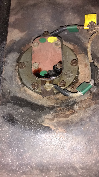
timely topic! just working on the fuel sender unit for my 140… your pics lead me to believe that your fuel sender unit is on the top of the tank? mine is on the side, and has been leaking (of course!). I got the gasket kit from Moss - two gaskets, round one between the unit and the tank, rectangular one under the cover plate. removed the unit to give it a good clean before replacing with the new gaskets, and discovered that the bottom terminal screw, which has a ground wire sneaking out beside it, has a fibre washer around it, as well there is what looks like a fibre flat washer on the outside of the sender, at the lower terminal, presumably isolating the terminal nuts and wire etc from the body of the sender unit. Has anyone ever go this deep into one of these? this is were my leak has been coming from I’m sure, and I need to replace the fibre washers, haven’t found a source, and so far haven’t thought of a “backyard” alternate or solution! Any ideas appreciated!
The shaft that goes through the body with the float attached is not sealed, so fuel gets inside that little chamber. So it needs a good seal inside and outside at the screw terminal.
One of the seals on the screw terminal is a sleeve that fits through the wall of the chamber, thus isolating the screw electrically from the body. Rubber vacuum hose would work there.
I found some small fiber washers at my local hardware store.