Now the bellhousing is again temporarily fitted, so that we can set up the hydraulic throw out bearing. Which brings us to our latest minor challenge.
When completely collapsed, the throwout bearing requires .150 clearance between the face of the bearing and the clutch fingers. This nifty tool from speedway takes all of the guesswork and math out of this process.
What the nifty tool told us is that the throwout bearing is about .200 long. In other words, I need to get it back about .350 to make everything acceptable. No good way to do that.
I selected this throwout bearing because Ram says it is specifically required for the T5. That might be true for T5 in a Ford product, but it’s not gonna work for me. Fortunately, Ram makes a slightly different bearing, which is about an inch shorter. I’ve ordered one of those, will be here early next week, then will return to the set up process and shim the throw out bearing out until it’s at .150, as you would normally expect to do.
What I think I need is a combination of the new input shaft bearing retainer that came with this bearing, and Ram’s other, shorter throw out bearing. We shall see.
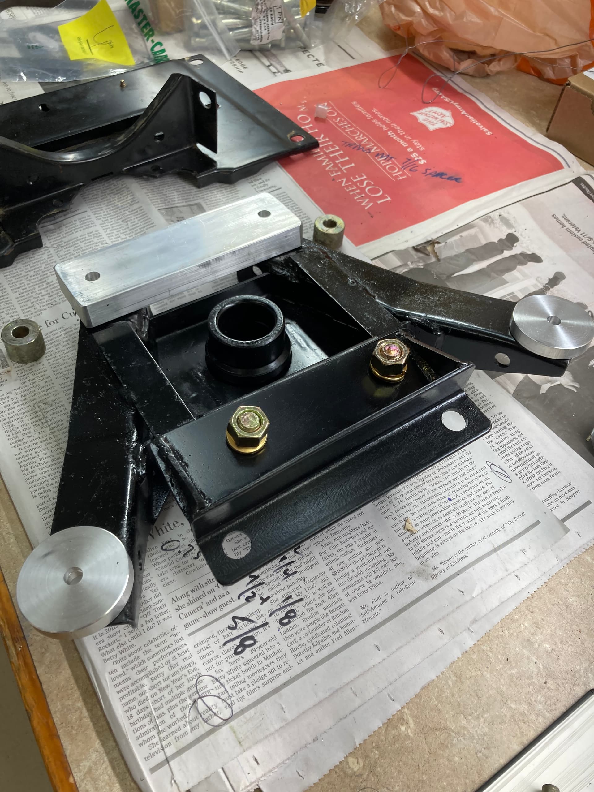
Meanwhile, we have other things to keep us amused. Here is the trans mount painted, with new spacers, ready to go in the car. The bar spacer is is the same height as the stock round spacers, I just happened to be doing a McMaster order and thought it would be good to have a bit more surface area. The front spacers are the right thickness to set the proper output shaft height, and again they are large diameter to give more surface contact.
(Update: I just noticed the front mounting pad is upside down on the picture below. Just need to unbolt and flip.)
Clutch mc detail. The Jag MC has two ports which are 3/8 NF thread, and designed to seal with a copper washer. The ports are identical. I shortened up a 3/8 NF bolt and used that to plug the port I’m not using. I made sure it did not cover the vertical pressure hole on the inside.
Clutch plumbing is all -3AN fittings. I found an adapter that is typically used when converting to braided brake lines, 3/8NF one side, -3AN on the other. The copper washer it came with was a bit sloppy for my taste, so I drilled one from my inventory and got a better fit. I annealed both washers before using them.
I wanted to run the clutch pressure line underneath the brake reservoir mount, but there’s just too much stuff under there already. In particular, the hood release cable is right there.
Since I am waiting for parts, the other thing I got done this weekend was to top off the diff, which was about a half a pint or so low after the pinion seal change. That job is every bit as nasty and unpleasant as I remembered it being.
Yes! And I am embarrassed to admit that I have that mod on my car. I just figured what the heck, it’s already way up in the air, I’ll just get under there and do it the old way. That way I don’t have to remove stuff from the boot, etc. About the time I had gear oil running off of both elbows was when I decided that I had chosen badly.
That’s funny! I thought that it was you that had cut the hole a couple of years ago until I read your post.
My wife is wrong- I don’t have brain fog after all.
I have been having a good time reading through your account of the trans change, thanks for posting so much detail and pix to go along with this!
I had done a switch to a Tremec TKO 5 speed a number of years ago, and I offer some bits from my recollection of this:
Your engine is a Marelli model- my '90 clearly is, also. Thing is, the pilot bore in the cranks of these engines tend to measure 0.725". This is a tad smaller than pre-89/90 Marelli engines, and so a pilot bush sourced from the usual Jag parts providers will likely need to be turned down somewhat. The speed shop I dealt with suggested 0.7265, or, an interference fit of about 1.5 thou. They counseled that if this was too tight, you would have trouble shifting the trans, too little and the bearing loses it’s function somewhat, as it is sloppy in the pilot bore. FWIW, the ID of my pilot bearing was 0.591, matching up to the TKO’s input shaft pilot diameter. Turned out that my speed shop’s recommendation was dead on- works great!
I noted you counted the teeth on the flywheel- NICE JOB! Since yours is a Marelli car, there is an engine speed sensor that reads the tooth passage to advise the ignition computer. Different number of teeth means a slightly different speed calculation from what the engine’s actual is. Not sure how important that is to Marelli computations on advance, but figured you’d want a head’s up.
I see you have had AJ6 Eng. stuff done to your ECU. You will definitely want the overrun cutoff deleted before you start driving the stick. It will stall out at intersections and be very annoying if this is not done.
Very interested in the ratios 1-5 on the T-5 box, especially since you are backing it with the 3.54. My TKO has the 3.27 first gear, and the steep OD 5th, and I run this against a 3.54 diff also. I wish that I had taken the time to fit a sensor wheel to the 3.31 diff I had around, and used that one instead of the 3.54 with that TKO gear set, but, the car is a great around town car, very responsive, if a bit short-legged. Had I to do this over again, I would splay the 5 gears in a close ratio manner, starting with a 1st gear under 3.0, numerically, when running the 3.54. Ideally, though, I am keeping a watchful eye for a Richmond 6 that has the ratios splayed similarly, but across 6 gears- they are not often coming up on the used market though.
Good info and advice on the bell fitment and checking the runout. Somewhat empirically, if the pilot bore of the bell is off by 0.1", I would guess you’d have a devil of a time sliding the trans into place. But it is good practice to check that run out.
Good advice on getting the flywheel/pressure plate assembly and the drive shaft (prop shaft, I suppose, I should say ) balanced. Good money spent, there.
Thanks again for continuing to post on this adventure!
You machined the bottom flange of your bell so that you could refit the inspection cover with the Marelli speed sensor. Nice work!
I went at this differently: I sourced an inspection cover from a pre-Marelli V12, and then found the location along the circumference where that sensor should be located. I filed a flat on the bell housing rim, and then used a die grinder to cut a notch in the bell to admit the sensor. I then drilled and tapped the mounting holes for the sensor bracket. Ended up being much easier to do. Only thing to watch for is to ensure you measure the sensor face to ring gear teeth clearance, and make sure it is to spec. I had mine initially misadjusted, and car quit on me during the first outing, once the engine got warmed up well. I reset the clearance, and everything worked as it ought.
Hi Mike-
Thanks for the detailed thoughts! Good feedback and questions!
A few notes, FWIW:
Pilot bore. My numbers were a bit different:
Bore in crank: .750
OD of pilot bearing: .752 (I used the bearing for a SIII Etype)
Input shaft OD: .668
FWIW some Richmond 6-speeds also have a .668 input shaft. If you end up with an OD of .725 and and ID of ~.668 you will not have very much bearing left…
Although the pilot bearing was a nice slip fit on the input shaft of the trans before I installed it, I built the nose of my install tool to match the input shaft of the trans. So that after the bearing was in I could confirm that I had the same nice slip fit. Just an extra precaution/test.
Flywheel teeth:
Agreed, the ESS input was one reason I counted teeth.
Stock flywheel: 160
Fidenza flywheel: 162
The net of it is that the EFI ECU will think the engine is turning about 1.1% faster than it actually is. Shouldn’t matter.
Overrun cutoff:
Agreed. This was removed from the ECU when Roger did the work. He even wrote “manual” on the sticker, which I thought was a nice touch Once the car is up and running I need to send him my original ECU for the same treatment, so I have a matching spare.
Trans ratios:
1st: 2.95
2nd: 1.94
3rd: 1.34
4th: 1.00
5th: .63
Based on our Etype experience I am pretty comfortable with these. I could see 3.27 being too low for 1st. FWIW the TH400 is 2.48 in 1st, but that’s not a great comparison as the torque converter makes that seem lower (higher number = lower ratio) We ran a 3.07 diff in the Etype for awhile, that was too high. 3.54 diff is perfect for that car. Worst case I can have my spare diff re geared with a different ratio.
Re: the speedo sensor, my Plan A is to convert to GPS. I will do a separate thread on that when I get to it. I think it will be pretty easy and cheap. My spare diff is the original, so I can put the speed sensor back to factory if I end up going that way.
5,6: Bell runout and balancing. Agreed. It doesn’t cost much more to do the job right!
Engine speed sensor:
Originally I thought I was going to have to take your approach. Then I saw that with about an hour on the mill I could retain the factory setup that has served well for 32 years, which seemed easier to me than drilling and tapping and gapping the new bell. Although, checking the gap is on my list of things to do. ROM calls for .018-.042.
If one is running a steel bell then cutting on the bell is a bit more work for sure. Glad to hear you were able to make another approach work, always good to have options!
Fingers crossed the new TO bearing will show up today and will fit like I think it will. That is almost the last hurdle. Getting the travel I need from the clutch using the Jag m/c is my last worry. My estimates say it should work fine, but of course the proof will be when it actually does.
Good ratios, those, a 2.95 first should match up well with the 3.54, I agree.
On the pilot bearing: yes, I think it was the engines produced 1990 and later that have the bore dimension I quoted. I thought maybe it was keyed to when Marelli came in, in the late '89 production, but I see from your experience that it is indeed 1990 and up. Some guys actually took a grinder to the crank pilot bore to open it up (!)- it’s in the jag lovers archives somewhere. You are dead right about the pilot shaft diameters- there isn’t much meat for the bearing in the case of the larger pilot diameter.
I think that the Keisler kit I had featured a Ford spec TKO, but with the pilot tip turned down to the 590 level. It definitely had a Ford spec tag on it when I got it.
Lots to consider when putting one of these manual boxes into this car-
Alrighty then. New throw out bearing arrived, and we are back at it. Good news! Our nifty tool confirms that the face of the bearing will be “behind” the clutch fingers. If you compare to previous pic, you will see that this is the “shorter” GM-spec bearing. I will update the part numbers given earlier in the thread.
We want .150 minimum between the bearing and clutch fingers. We’ll shim the bearing out using the provided shims. There are two ways to confirm the clearance. I will do both to be extra sure.
The eyeball meter said 3 shims looked about right.
Then we use them as, well… feeler gauges. Looks pretty good. Note that we have not moved the tool, it is still at “bellhousing to clutch fingers” depth.
This is pretty basic stuff, but screw it up at your peril. The only way to adjust later is to pull the trans.
Now that we know the shim stack needed, we need to trim the anti-rotation stud to just be long enough when the bearing is fully extended. Otherwise it could possibly hit the pressure plate.
Next we need to re-check the input shaft end play, because I ended up using the bearing retainer from the first Ram bearing. The second bearing does not come with a bearing retainer, so if you’re going to do this project with these parts, you need to buy a separate bearing retainer. A few notes:
Here is the original (black) retainer next to the new one. First, the original will not work with either Ram bearing. Not only does the “step” at the base of the sleeve get in the way, the sleeve is also larger diameter. Apparently this is a Ford-style T5 thing.
The original is also aluminum. Paul warns about these in his book and recommends upgrading to an iron retainer, which the new one is.
Since I did not change the input shaft or the bearing, I was hopeful that the critical measurement between the two retainers would match, so that I would probably not need to re-shim. What we need to know is the difference between the outer mating surface and the inner surface where the bearing shell and shims rest. The height of the flange is irrelevant.
Good news, both units clocked in at .243 between the surfaces. I would hope that would be the case, these are precision parts and should match up.
Just as a test, I went through the shimming procedure, which calls for zero end play, and no more than .003 crush. I bought a pack of shims from Allstate gear, so I was ready to go.
Next, we attach the fittings and lines to the bearing. The antirotation ear is a handy place to grab in the vise. The bleed line will be the highest port, and I went ahead and put the bleeder plug in so that I wouldn’t lose track of which was which. Ram charges $30 for a “bleed kit” which includes a piece of -3 AN line and a fitting to go in the throwout bearing. It’s kind of a necessity, I don’t have any idea how you bleed the thing if you just put the plug right into bearing, you’d never get to it.
Note: use Teflon tape on the fittings that thread into the bearing. Then are NPT. Do not tape AN fittings.
Next, we clean the mating surface on the trans case and goop everything up with
Perma Tex ATF gasket maker. (These transmissions run ATF.). Tremec was not shy with the sealer so I was not either. No gaskets are used in the T5.
The throw out bearing must go inside the bellhousing, you can’t just leave it on the trans and install, it won’t fit thru the hole. Option 1 is to put the bell on the trans and then the TO bearing then install the whole works. Option 2 is to put the bell on the engine then position the TO bearing up in there and try to slide the trans in. This is more like a conventional install with a fork. But there is nothing to hold the TO bearing in place. However the lines are stiff enough that it looks like it will sit still until I can spear it with the trans. Also gotta line up the antirotation stud. So option 2 it is. Much easier to bolt the bell up with no trans attached.
About this time I am rather pleased with my progress. Well, you know what they say about how to make God laugh… The trans slides in well, and then stops. It won’t go in the last 1/4 inch. WTF?
After some muttering I decide it has to be the input bearing retainer hitting the clutch disc hub. I pull the trans out and measure and I win the prize. Grr. So, we pull the bearing retainer back off and give it a 3/4” haircut. It’s now just longer than the TO bearing sleeve.
I really should have thought of this before. The retainer snout does nothing to support the input shaft. That’s the job of the pilot bearing and the input shaft bearing. It is only there to guide the TO bearing. So cutting it is no problem.
Or is it? Now I am wondering if there is a chance I will be at the end of the splines on the input shaft. They do taper out right about here. That could jam up the clutch disc. Will it be able to slide back a bit when released?
It will probably be O.K. But I can’t convince myself. So off come the bell and the clutch so I can test. Good news, the disc slides freely all the way back. Phew.
(The clutch disc will never come back all the way like this in use. The pressure plate won’t let it.)
Now, to triple check, the clutch and bell go back on, and I fit the trans again with no TO bearing so I can see. If you zoom in you can see the blue green tape right at the end of the bearing retainer, then some splines, then the clutch hub. There are now about 1/2” of exposed input shaft splines before the clutch disc hub. Plenty of room.
So now the trans is back in the car with the TO bearing, hopefully to stay. Tomorrow I will get the heat shields and trans mount put back in, and probably the driveline. Then we can bleed the clutch and make sure we are getting a reasonable release point.
2 Likes
Kirbert
(Author of the Book, former owner of an '83 XJ-S H.E.)
141
It never would have occurred to me to install the bellhousing first. I dunno why, but it always seemed SOP to bolt the tranny to the bellhousing and then install the assembly.


 ) balanced. Good money spent, there.
 Once the car is up and running I need to send him my original ECU for the same treatment, so I have a matching spare.


