It’s all white? How do you plan to mark the different leads?
Permanent marker. Looks like what I have to deal with immediately is the wiring to coils. They appear to be all white with purple, black, and brown tracers.
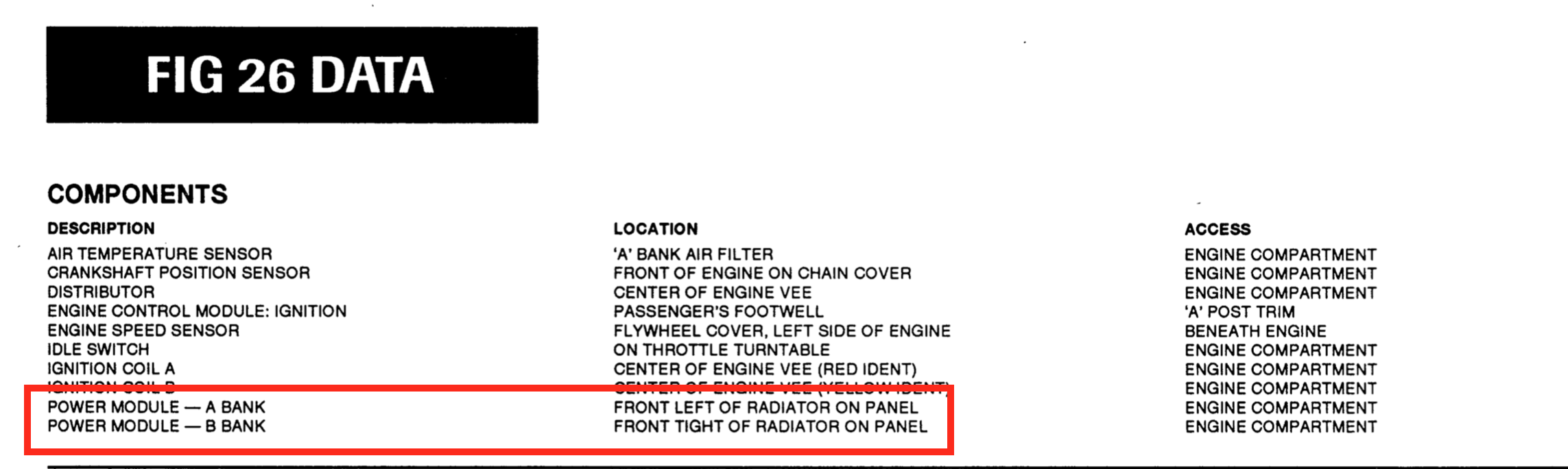
Bank B power module shows the white/purple with black, red, and blue. Wiring appears to have no big insulation gaps for possible shorts. Have unplugged the module and it smells burnt. Will inspect the wiring closer tomorrow and probably just swap the A and B modules and see if bank B works and A does not. The part number on it is the correct Marelli number.
It is mounted on a different heat sink made of aluminum. The conductive paste seems fairly fresh.


I have found Sharpie permanent markers not to be particularly permanent. The writing fades with time until it disappears altogether.
I’ve got a new set of HT leads to install. I’m going to label them with a Brother label maker that has a function for printing wire wrapped labels. Then I’ll cover them with clear shrink wrap. Hoping that will survive the heat in the vee.

I saw the purple and assumed it to be factory wiring marked with indelible ink. Might need to look a little harder for some purple shrink tube.
That’s an idea. Have some old purple wire. Can just strip off some insulation, put it over new wire, and clear shrink tube it on.
Nice, but in my case with Superblack, what to do with those 3-part connectors where the wires attach to the coils? That’s right where the wiring has cracked … 
Hey Dallas…there is a product called Plasti-dip which is a thick liquid that dries into a thick plastic coating. I wonder if that would work to re-insulate those wires to connectors ? I have bought at Harbor Freight in the past.
Interesting, JimD. We have a HF not far from me, so will check it out this week. Thanks! 
Walmart had the best price I found. Ordered the pin connector removal tool to move wire and pin from socket. Will use liquid tape and heat shrink on wire up to connector. They had it in stock.
I bought gasket material for coolant gaskets, works fine. I tried the cereal box idea, but it only works once.
I used a tiny amount of red rtv silicone on the distributor and stuck it to the cardboard. Trimmed it with an exacto knife in 24 hrs and it went on fine.
Interesting, Bret. I was wondering what the max temp range for it is, and it says up to 275 deg. F… I would think that is good enough for the top of the V-12s. ![]() Thanks!
Thanks!


Was going to swap modules to see if B bank would work and A bank would stop. Peeled back the electrical tape and found the modules are wired differently.
The harness to A module has an incomplete jumper wire. It was running. Part numbers on both modules appear as direct fit on interchange charts. Any suggestions?
Terrible job by PO fixing the wiring! Here is the electric diagram:

Both ignition amps are the same and everything should work/look the same
Wire looks bad, stiff as a pipe. I have the wiring diagram and am confused. Seems besides the PO wiring modules differently they both look wrong to me.
I would expect jumper from black to red but not blue and red twisted together before plug on B module.
I would expect jumper from black to green , which is not, but not green and brown twisted together before plug on A module .
It also appears the ignition modules have swapped positions. The A module is in the driver side per ROM but passenger side on my car.


Any suggestions on how to proceed?
This is how they should be. Counterintuitive, but A and B bank amplifiers are not aligned with the said.
My A and B harnesses are definitely swapped. I just wish I knew which wiring is correct. It seems weird that A has the jumper wire from the joined together brown and green wires to black not connected and it runs. B has the jumper wire from the twisted together blue and red wires and it ran for 80 miles and crapped out on me. It has a bit of a burnt smell to it but looks ok.
I don’t want to run the good module on B harness and take a chance that it will burn up.