I’m ready to mate up the gearbox with my newly rebuilt engine (XK120) but before doing so I’d like your ideas on how to improve upon the clutch linkage for reliability, if needed? Specifically with the throw-out bearing yoke (C9780) and the bell crank (C3261) on the end of the shaft. In reading over previous postings I know the original parts are prone to failure as the taper pins don’t go all the way through. Would it be wise to weld the yoke to the shaft as some others have suggested in the past? And with the bell crank would it be a good idea to turn a pin that goes all the way through the bell crank and not just halfway inside? Note that my car came to me with a Mk VII (and later) yoke and bell crank. I don’t know what kind of difference that makes but they are still in very serviceable condition though I did note the yoke taper pin had sheared in two upon removal. Also I will be using the stock Borg & Beck setup which has already been balanced with the refaced flywheel (0.040" was faced off). I really want to avoid any premature parts failures here as my back isn’t what it used to be.
used an XK120 FHC and then an XK150 FHC as Daily transport for 14 years and prior to that drove an XK120 roadster 12000km in 6 weeks part way around Australia never had a failure or problem.
Check parts, New pins, properly lock wired.
I must admit on current 120 roadster resto I have machined a new cross shaft due to wear at ends
The bell crank and yoke components in your photos do not appear to be the ones sold by some of the usuals that are made from cast Chinese butter metal. As such, they stand a good chance of surviving for considerably longer. It is really important that the taper of the pins closely matches that of the holes in the shaft. If not, it will not take much time at all for the crank or yoke to move relative to the shaft, and once that happens things will go down hill fast. Therefore it’s important to ream the holes in the shaft with the appropriate tapered reamer to match that of the pins. I skipped this step (twice) and paid the price each time…
If I were to redesign the bell crank and yoke, I would have milled the cross shaft to accept a square or woodruff key(s). The yoke would have its key slot milled in an area with the most parent metal available. The bell crank would receive it’s taper pin protruding on both sides and not just one. As it is, I’ll modify the bell crank (and shaft end) but I’ll weld the yoke to the cross shaft and look upon the two henceforth as consumables to always be cut out and replaced during the next clutch replacement.
My observation is that the current taper pins suck. They are not accurate reproductions of the originals, which were bullet nosed. All the reproductions I’ve seen are too short and don’t extend through both side of the yoke, as did the originals.
My advice
(1) before designing your solution, I’d take a bit more time to study where the originals and the reproductions have broken. Many on the forum have had this part fail and can post pics and stories about the failure modes.
My old fork was likely a real Jag part (not reproduction). The hole for the taper pin was drilled up into where the base of the off-side arm connects to the cylindrical body. And not surprisingly, I found a hairline crack that went almost all the way thru the base of that arm … clearly precipitated by the hole which had removed much of the material where the arm meets the body. It only took moderate hand pressure to open up that hairline crack so in reality that arm was essentially broken off! Perhaps I narrowly avoided a fracture by replacing it when I did.
You may find failures elsewhere to be more common. On mine the pin was fine, and correctly safety wired to prevent it from loosening up. On my particular setup, I do not seen how a failure could occur at the pin. The force required to shear off that pin surely exceed the force of operation many orders of magnitude. If the pin had come loose then yes a failure mode could be the pin falling out. Hence the safety wire. And I could not see how the cylindrical body of the fork assembly could fail at the pin hole because the material is under compression. Most metal alloys tend to be quite strong under compression loads. The only place I could see a concentration of force at a potential design weakness was in the strength of the arms themselves and how they attach to the body. But, what the EFF do I know about this stuff? I’m not a mechanical engineer.
(2) once you feel know where the parts you intend to purchase fail, then you can focus on modifying that specific part to be more reliable.
I think the folks at Coventry Auto in the UK have done exactly this analysis, and they now sell a much improved design for the xk120. Were I to do it over again, I’d buy their solution. As it is now, I used their older design alloy TO bearing arm because it was clearly well thought out in design and it’s made of an durable alloy appropriate for this application. I cannot say the same for any other repro parts I found at that time. Plus, their part was the least expensive! The Scots don’t have a monopoly on being cheapskates…
I suppose it’s not acceptable forum etiquette to say which suppliers sell crap forks that break with sometimes catastrophic results. So I can only recommend CA
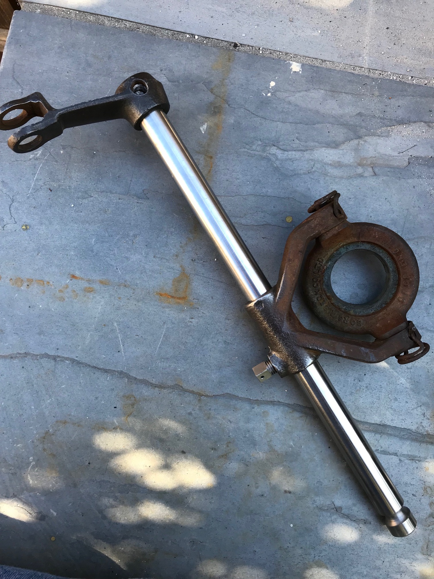
If you are talking about this fork, I would tend to agree. The finger side, where the original pins formerly protruded, is much thicker than the originals. I would note that I have seen two of the pins in the original forks shear off.
Again, my fork/ yoke was found to have part number C9780 stamped on it when I pulled it for rebuild. That’s the part number listed for Mk VII’s and subsequent. So, not original to my XK. Should be C582. Therefore, the one previous to this had either been replaced due to wear or, it too had cracked in the past. Upon attempting to remove this latest one, the pin would not rotate loose without some effort. Finally, it came loose – but in two pieces. So I’m thinking that even though this current fork hadn’t failed, over time the taper pin that had secured it had bent just enough so that, upon removal, the stress of removing a pin no longer straight was sure to break it in two. I like how Coventry beefed up this latest fork/ yoke with a gusset but note that this replacement, according to them, is made of aluminum bronze. Is that really advantageous over steel? It would be nice if they could include a second boss for a second taper pin – and special, modified matching cross shaft to match. Therefore, torsional stress would be absorbed by two pins instead of one. Anyway, as it is, I will be reusing this latest fork but may or may not be supplementing shear strength (at the pin) by welding it to the cross shaft. Finally, I gave this more than passing attention due to the many previous postings over the same complaint by others when doing an archive search.
Mike
That’s the one I like. Interesting to hear that the pins sheared off. Hard for me to imagine there is that many thousands of psi bearing on the pin. Well, perhaps the pins started to wiggle a bit, which would make them much more succeptible to breaking.
“aluminum bronze”
I believe it is strong alloy which stands up to repeated stress very well without work hardening very much. I have a grade 8 bolt thru my fork at the other end from the tapered pin. This provides double the strength, and I know that this added bolt won’t come loose because it goes all the way thru and uses a nyloc nut.
Here’s a quick run through of the math for the shear force on the pin, making some assumptions on the geometry for things I don’t have laying in front of me.
Assuming: 5/16 diameter pin, (0.3125" diameter, 0.077in^2 cross section), 3/4" diameter shaft, 12" long pedal arm length (guess), 100 lbs force applied to the end of the pedal arm required to release the clutch.
Summation of the moments around the center of the shaft:
0.375 inches * X = 12.0" * 100 lbs
solve for moment at X
X = 1,200 inch-lbs / .375"
X = 3,200 lbs
Shear stress at pin:
S
S = 3,200 lbs / 0.077 in^2 = 41,722 psi shear stress at pin. (single shear)
“shear strengths of carbon steel fasteners may be assumed to be approximately 60 percent of their specified minimum tensile strengths”
Internet search suggests tensile strength of a 5/16” bolt is around 7000lbs (grade 5). So by this rule of thumb shear strength limit is 4200lbs. If true there is relatively little margin relative to a 3200lbs load.
Proof load is lower than Tensile, and in our example could be around 4500lbs, giving a shear strength of only 2700lbs, below our example loading. This, would only apply, I think, if there was significant looseness or slip in the connection, allowing the pin to bend a tiny bit.
Furthermore I’ve always been told a bolt needs to be under tension to attain its design working strength. Is that right? I’ve experience suspension bolt failures (on a single shear mount) when the bolt wasnt tight. The lack of tightness allowed the bolt to flex side to side a very minute amount, and it broke with a classic back and forth deformation failure across the bolt diameter.
So maybe the flaws of the pin design are
(1) lack of safety margin in the basic design,
(2) pin which isn’t under tension like a regular bolt so it can’t prevent the possibility of a bit of movement in the shaft or fork body.
If so a simple fix might be to still the body/shaft for a couple 5/16 grade 8 bolts and properly tighten with locking nuts.
I also
Like the idea of a slot in the shaft/fork and a key, but the key would have to be long enough I’ve been told these need tight tolerances to have good strength.
The calculation above is for a pin in single shear, which is what you tend to see with the reproduction pins. The original bullet-nosed pins protruded from the back side, so they were functioning in double shear, so the stress at each shear point would be half of single shear. I have never seen a replacement pin that looked like it was anything other than mild steel, far weaker than any SAE/ANSI graded bolt.
SAE Grade 5 bolt produced from ASTM A449 steel allowable tensile stress is 120,000 psi. Rule of thumb allowable shear is half that, so 60,000 psi. The cross sectional area of the shank of a 5/16" bolt is 0.0766 in^2. 60k psi x 0.0766 in^2 = 4596 lbs. I have never seen any reproduction pin that appeared to be made from anything more exotic than common carbon steel rod, which has an allowable tensile stress of around 58,000 psi.
Yes. A bolt is generally properly torqued at 90% of its allowable tensile stress.
Note that when you calculate or estimate the applied load or its resultant tensile or axial stress, you use the minor diameter at the thread root, not the shank diameter. For a course thread 5/16" bolt that would be 0.2431" (2a fit) and for a fine thread bolt that would be 0.2603 (2a fit).
120,000psi x 0.2431 x 0.90 = 26,255 lbs tensile force required
120,000psi x 0.2603 x 0.90 = 28,112 lbs tensile force required
Right so I think Coventry Auto did a good job redesigning this problematic part. If you use a fork from someone else best drill thru and put a grade 8 bolt through the whole thing.