What follows is a summary of topics covered in the previous five elements of this thread
SUMMARY OF PREVIOUS THREADS I thru V Part I - Introduction of Hobby Shop and removal of engine/transmission Part II - Removal of all wiring harnesses, dropping fuel tank, stripping the car of all ancillaries and cleaning asphalt coating from under-body/bonnet Part III - Engine Tear Down, Removal of Heads, Chrome to Chrome shop, Prep for and actual Painting of the Jaguar Part IV - this thread covered quite a myriad of topics: A comprehensive matrix of nickel and cadmium platers // Procedure for removing crankshaft // Remove timing chain, guides and tensioner // Repair Timing Chain Cover (aluminum welding) // V12 Exhaust system options // Removal and ultimately Replacing Oil Pump ($$) // Check Cam Sprockets for reuse // Challenges of removing 6 stuck pistons/sleeves (significant portion of this thread) – including a trip to a machinist; spread over a wide range of posts // Discussion of glass beading and/vs vapor blasting // Return of Chrome Part V - this thread covered: carbs and dizzy back from rebuild (with contact data) // options for A/C compressor // installed left and right side wiring harnesses and Bulkhead Harness // challenges attaching Bulkhead Harness Grommet (C30670) // Elastrator as a possible tool to solve issue // more on vapor blasting – a definitive discussion // purchased a non-boot lid seal during a group buy to use as a boot lid seal // started install of distributed compressed air from the compressor.
Spent some time trying to match the original harness (hung over the scuttle) to the new Bulkhead Harness in the car. Questions follow.
First an orientation for those not familiar with Series III (note there is NOT a circuit for a radio – but I have a working radio in the car when parked).
Anyone know what “D.I. Flashers” are on Fuse 6? Directional ** Indicators (AKA, turn signals)?
First question:
What is this (3 views shown)? (It is attached to a wire attached to the upper right hand corner of fuse 7 by the white-ish wires and then mounted to the dashboard).
Furthermore, the white-ish wires on the original harness all look alike, no tracers (see top photo of last three attached). The white wires on the new harness are white, white with 2 thin red tracers (shown), and white with a thick red tracer - not shown (the bigger/thicker of the three in the photo) as shown here:
So - does it matter which of the new, white wires this blue thing is connected to?
X-X-X-X-X
Next: 2x white-ish or beige wires (on the original harness) come out of the harness and attach to the topmost terminals on Fuse 3 (see Photo below) opposite the violet wires. It’s hard to trace the wires on a photo so take my word that the wires with the “Fuse 4” tag on them do what I just said. What is even harder to see is that there is a jumper wire connecting Fuse 3 and Fuse 4 (it shows better in the next photo - the jumper is black taped to one of the white-ish wires). I plan to reuse that jumper wire – but: what does it do? Not an earth-shattering need but I’m trying to better understand the wiring. What is the function of the jumper wire?
This above photo is of the same bundle of wires but focused on the other side of Fuse 3. It shows 4 violet wires attached to Fuse 3 with the 5th one (with a black collar on it) going into a join and coming out brown with a yellow trace and with an in-line fuse – to the other side of the same fuse. WTF? None of the violet wires on the new harness have the black collar. Does it matter which of the 5 violet wires I do this two? Is it necessary to keep this in-line fuse? What is going on here?
Hi Craig.
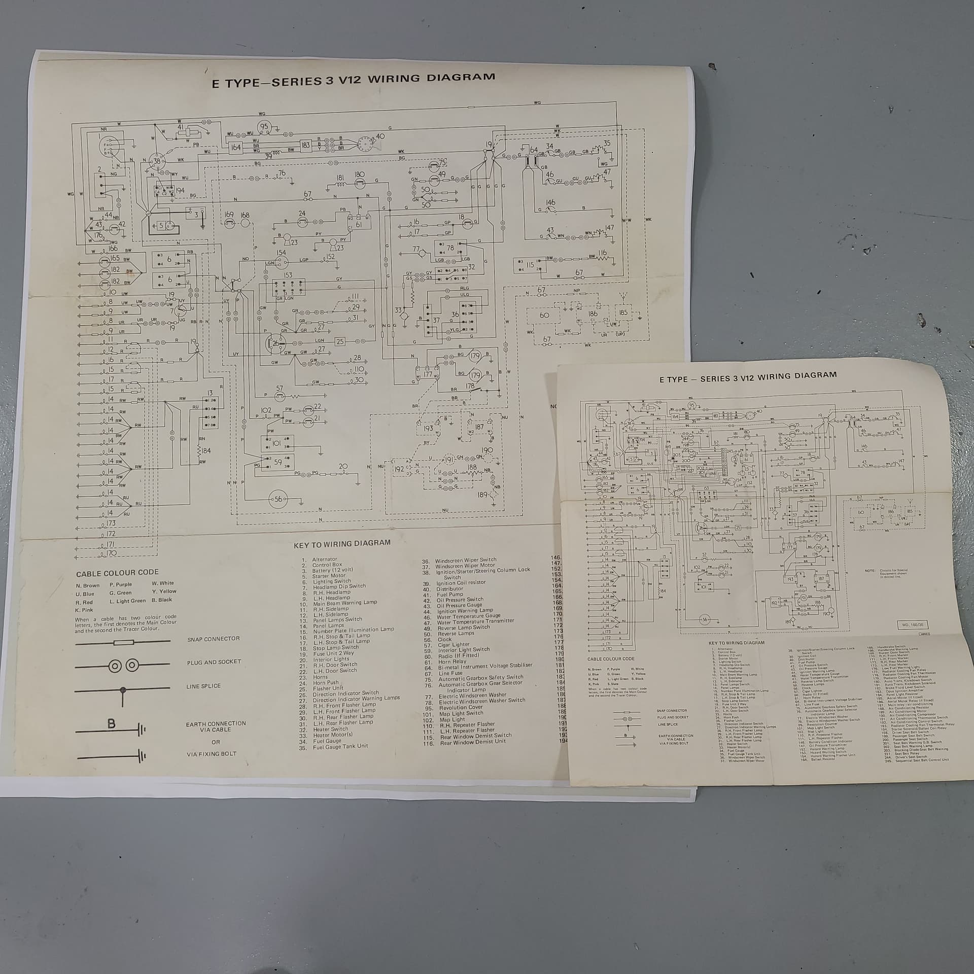
First, do you have the factory issued Wiring Diagram than came with the car? The diagram should be labeled: WD.160/3E If NO, obtain one!
Yes, there is an “accessory” circuit feeding power to a radio. There should be a WK (White/Pink) wire from fuse #7 to the radio power lead. That circuit also has an inline fuse. Accessory items are shown as dotted line traces. Along with the radio the schematic shows the wiring/components for an electric aerial system.
The round/blue thingy is a filter capacitor (C45222(C42610)). Jaguar used several as noise filters in circuits such as Radio, Fuel Pump, Instrument Voltage Regulator, and Battery B+ multi-connection. The capacitor captures line noise, filtering it from the circuit. Clip the black lead connector to the F7 fuse block WK wire (radio) and slip the metal part of the capacitor under a suitable bolt nearby as the ground side. Filter capacitor mounted to Fuse #7 WK (radio feed) wire.
Filter capacitor mounted to Instrument Voltage Regulator.
If you don’t have a wiring schematic you can down load one from the XKE Data web site. There may be a few components (seat belt warning logic box, etc.) that’s not found on your car. Just ignore them.
If you’re not sure how to read/trace a wire/circuit invite Wiggles down for an instruction session over a couple of cold one and a good piece of grilled BEEF!!! The wiring Excel spreadsheet I sent should help with wire tracing by color.
D.I. Flashers = Directional Indicator Flashers (items 26 thru 31) - S3 schematic.
For the F3 tyo F4 jumper wire again, refer to the wiring diagram. Make sure you install the jumper on the correct side of the fuse blocks!
More later on your additional questions.
Make sure you installed correct amperage fuses. British fuses don’t cross - Amp to Amp - American fuse standards per se. Factory installed fuses are BRITISH 35 amp/ 17 amp continuous rated. If you don’t have the British/American cross chart let me know and I’ll post it.
Happy Trails,
Dick
Note: The NY (Brown/Yellow) wire with inline fuse should be for the radio. The wiring diagrams shows that wiring as N. No explanation why Jaguar used NY! Another Jaguar mystery!!!
One question: Why didn’t the painter paint the inner dash areas?
Tip: Have your local print shop enlarge the factory schematic to fit large foam board. Glue to board. Much easier to read/use!
A couple of quick answers while I digest all the info you provided.
I find it ironic you used one of my own photos of the capacity to explain its function to me . (I also have another capacitor attached to the instrument panel-- haven’t explored that element yet.) Also – I noted your caption was far more accurate than my original attempt at a description.
I assumed a wiring harness was a wiring harness. I have 3-5 of them - the one I use most is full color version I found on eBay (easier to find/trace wires // 18"x11" // and fully laminated) – and a B/W over-priced wiring pamphlet I purchased with the harnesses. I am 98% sure I have 1or 2 copies of what may be an original diagram. I need to compare the part number on it/them. I haven’t used it/them very much because the print is so small. That may change.
I have had @Wiggles down several times – one or two of those future visits apparently needs to focus on automotive electronics. His job is timed to the school year so I may be able to entice him down more frequently as summer approaches.
Thanx for decoding D.I.
I am aware of the difference between US and UK fuse ratings. I still have a fair number of LUCAS fuses (I know to do a continuity test and to clean off the rust/corrosion/gunk on the fuse ends). It is a good reminder, though.
Cuz I asked him not to, for 2 reasons:
SILLY - I wanted to retain a bit of the original color (Sable Brown) – not even close to my favorite colour
REALISTIC –
It will never be seen by any one in the next several decades unless replacing a fuse – and for at least 7-10 years that’ll be me.
I know my short-comings. At the top of that list a total inadequacy with anything dealing with automotive electrons. So, leaving the underside / innards of the dashboard intact gives me witness marks to aid in reassembly. This – combined with my OCD – is a challenging combination and goes a long ways to explain the speed that I am NOT moving at in my rewiring efforts of my Jag.
AND - My anal retentiveness has set a (perhaps unrealistic) goal of the engine starting on first attempt AND all systems functioning properly.
Many years ago, when I had a customer who wanted me to put a V6 into his four-cylinder Nissan Pathfinder, we obtained the engine, and then found out that for that particular year Nissan Pathfinder, and that model alone, there were 26 wiring harnesses.
Over the years, it has been the exception rather than the rule to find a wiring diagram that exactly matches the car I was working on.
OK Dick
I checked my mini-library of wiring diagrams.
GOOD NEWS: I do in fact have WD.160/3E. There is another number just below and to the right of that number: 4992D. I mention this cuz the wiring diagram in my Repair Operations Manual (while missing the WD.160/3E notation) has 4992B on it. I assume it is an earlier version than the stand alone diagram.
BAD NEWS: The full color // 18"x11" // and fully laminated version has no numbers on it at all. It was made by Classic Car Wiring dot com.
Sooo - I reckon I’ll set aside the pretty colorful one, and squint at the WD.160/3E diagram.
Thanks for the clarification on the various versions of diagrams
Craig,
All’s not lost. Since you have the factory wiring schematic you’re in business… There must be an Office Supply company near by so take that original Jaguar schematic to them and ask it be enlarged as big as they can make it. 24" x 36" should provide you a very readable schematic. From our local Staples Office Supply store I purchased a can of Scotch Spray Mount adhesive - 10.25 oz - $22 and mounted the enlargement on a sheet of foam board. Makes spark chasin’ sooooo much easier and makes a nice wall decoration too! The factory schematic has all the component numbers I cite in the Excel spreadsheet. Getting older isn’t fun so such enlargements are not only helpful ----- BUT necessary IMHO… Ha Ha
My enlargements are 4992D vintage. Has everything you’ll need to put Kitty back to purring again. With an Ohm meter, check each circuit, verifying all BEFORE even thinking about applying electrical power. Lucas smoke isn’t healthy!!! I also enlarged Paul Spurlock’s (Jagdood@gmail.com)schematic, downloadable from XKEdata.com.
There are a couple of changes Jaguar didn’t include so if you are interested PM me for schematic updates. Another thing about enlarged schematics: You can make notes, draw, etc. to aid in recall. I’ve added lots of info on mine. Saves me time.
I spent the day dissecting and trying my best to understand the ins and outs of just a part of just one wiring harness (admittedly the most {or maybe second most} complex of them all).
I will preface my question by saying I need guidance at the Wiring-101 level. But it is even more basic than that.
Example: On Fuse 7 there are several green wires: two are simple, single wires with a spade terminal, one is a pair of wires attached to a single spade terminal, and the last is another pair of wires attached to a single spade terminal but one has a brown collar around it.
In this example the original harness was easy to copy wire by wire - the new harness and the original matched perfectly. I am confident the new wires exactly parallel the placement of the old (except it is entirely possible I switched the 2 simple, single wires with a spade terminal). The wiring diagram does not show a pair of wires attcached to a single spade terminal
In other instances, it is not so clear which (fill in color of) wire attaches to which of the 4 or 6 terminals on the fuse block. I.E.: on the right side of Fuse 3 there are 5 purple wires that need to connect to 4 terminals. The 5th one (but I don’t know which) connects (via a join and in-line fuse) to a wire that becomes Brown-Yellow attached to the left side of Fuse 3.
The N vs NY wire is not my concern. Determining which one of the five purple wires is correct is my issue. The original harness had one purple wire that was longer than the others and with a black collar on it. The new harness - not so. How do I proceed on this one issue??
Assumption - it doesn’t really matter which of the 4 or 6 terminals on the fuse block (fill in color of) wire attaches to cuz the electrons flow thru the fuse to all the terminals.
Always Right?
Mostly Right?
Sometimes Right?
Those fuse blocks were adequate for a car with little electrics, but remained and had to accommodate many extra components by 1974.
That is why there are double spades. It doesn’t matter how that is arranged. What matters is the base colouring of the wires which was common on all Lucas cars.
Brown is unfused and always live.
White is ignition fed brown
Green and red and fused whites.
Purple is a fused brown.
The tracer indicates the component type.
The sleeves are afterthoughts or optional items for certain markets, e.g. hazard light or seatbelt warning system wiring and simply differentiate two similarly coloured wires close to one another so the feed to the exotic new component is “the extra one”. Your purple sleeved wire is likely whatever was added last onto the car by comparison with a 1961 etype diagram, so compare backwards. The wiring diagram (or a previous copy) may give you clues about that if you look carefully. The collars should be at both ends of the wires. If not, you can still use a meter to determine which wire is which.
It doesn’t matter which of the 4 or 6 terminals on the fuse block you use. The electrons only flow when the component at the other end is switch on and the circuit is completed. (Clue is in the name - “circuit”.)
This will be an excellent time to measure the current draw of each component, make a chart and then fit lower rated fuses than 35amps where appropriate.
Craig,
I understand your conundrum.
First, identify what wiring harness(s) you are wire tracing. If your tracing Instrument wiring (Bulkhead Harness) those terminate in connectors which plug into the various harnesses throughout the car. The easiest way to go that route is to connect all to their respective harnesses then trace each wire to it’s intended end. Some connect to the fold down dash (i.e. Clock) components.
First, do you own a Volt/Ohm meter -used for tracing wires? Are you familiar with its operation and feel comfortable tracing a wire/circuit while referring to the wiring diagram?
Your best bet is to seek help from someone local who can effectively trace wires/circuits. They may be able to give you hands-on training to show you how it’s done.
Jaguar left many small details out of wiring diagrams, repair manuals, etc. We now just have to deal with it! Aftermarket dealers, while doing their best, may introduce more “unknowns”. Only with a wiring diagram and a VOM meter (or circuit tester) will you be assured your wiring is correct before applying electrical power!
Wiring is not basic when you’re doing it without experience! Seek help (Wiggles, etc.) if you’re not sure. Internet instruction is poor verses on-site hands-on help and training.
Marek - I would have thought so too, but I drew this aid to ensure I connected the wire(s) from the bulkhead harness to the proper fuse terminal.
I know it’s hard to read but the point of my posting it is that while some fuses are loaded (Fuse 3 has a wire attached to every terminal), others are absolutely barren. I circled in pencil those terminals that do not have any wire attached – there are a bunch of them.
Some examples:
Fuse 1 - 3 of 8 terminals have a wire attached
Fuse 2 - 2 of 10 terminals have a wire attached
and my favorite
Fuse 8 has 8 terminals and is totally devoid of any attachment
But in comparison, Jaguar had very few wiring harnesses. I am pretty sure all LHD V12 E-types have the same harness.
My early LHD OTS #1S20183 has all original wiring. It has the factory (non documented) radio speaker wiring, all the wires for the A/C version with center cubby box cigar lighter, power antenna wiring etc although it never had any of those devices.
Spent another day playing with wiring harnesses, wiring diagrams, and my Fluke multimeter.
Primarily doing simple/basic continuity checks - between wires and checking a dozen fuses (trashed about a 1/3 as useless; either broken/burnt innards or terminal ends corroded beyond correction).
Am starting to get the hang of this wire tracing thing; at least at the elementary level. ID’ed several wire ends that belonged to each other – some on opposite sides of the car. Good feeling.
Also had the epiphany that I am waaay early in trying to trace wires with only the one harness in place and no accessories/assembles back on the car. I incorrectly reasoned that if I checked each wire as I added it, I would reduce errors. Once all accessories/assembles are at least temporarily placed/attached (grounded) and the other harnesses at least laid in place (but connected) I will have a much more logical method to trouble shoot the installation.