Craig Restores a Series III - part VII

SUMMARY OF PREVIOUS THREADS I thru VI
Part I - Introduction of Hobby Shop and removal of engine/transmission

Part II - Removal of all wiring harnesses, dropping fuel tank, stripping the car of all ancillaries and cleaning asphalt coating from under-body/bonnet

Part III - Engine Tear Down, Removal of Heads, Chrome to Chrome shop, Prep for and actual Painting of the Jaguar

Part IV - this thread covered quite a myriad of topics: A comprehensive matrix of nickel and cadmium platers // Procedure for removing crankshaft // Removing timing chain, guides and tensioner // Repair Timing Chain Cover (aluminum welding) // V12 Exhaust system options // Removal and ultimately Replacing Oil Pump ($$) // Checking Cam Sprockets for reuse // Challenges of removing 6 stuck pistons/sleeves (significant portion of this thread) – including a trip to a machinist; spread over a wide range of posts // Discussion of glass beading and/vs vapor blasting // Return of Chrome

Part V - this thread covered: carbs and dizzy back from rebuild (with contact data) // options for A/C compressor // installed left and right side wiring harnesses and Bulkhead Harness // challenges attaching Bulkhead Harness Grommet (C30670) // Elastrator as a possible tool to solve issue // more on vapor blasting – a definitive discussion // purchased a non-Series III boot lid seal during a group buy to use as a boot lid seal // started install of distributed compressed air from the compressor.

Part VI - this thread covered: processes of wiring new bulkhead harness to the 4x new fuse boxes // variations of Series III Wiring Diagrams // MarekH: Jaguar Wiring 101 // how-to regarding Home Made Circuit Tester for less than $10 // Comparo of newly cadmium bits and tubes to old // rebuilding wiper motor // receipt of new Exhaust System // comparo of incandescent bulbs to LED equivalent // camparo of mechanical brake light switch vs hydraulic // tricks to re-installing pick-up/return lines and the ins and outs of the in-tank fuel filter // receipt of all bits to rebuild heads and choosing a machine shop // YouTube videos covering the wiring of the 10x switches on the gauge panel // a source for better-than-new Front Upper A-Arms (AKA wishbones)
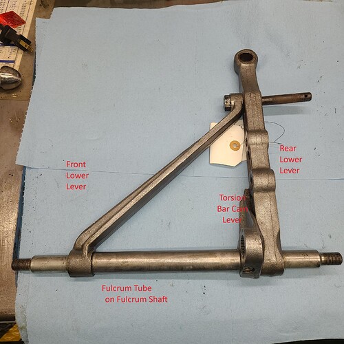
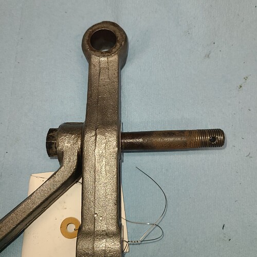
I spent Saturday attempting the disassemble the lower wishbone.

I got the easy stuff off: castellated nuts, washers, fulcrum shaft housing blocks.
But I was stymied in separating the main components:

  • front wishbone lever
  • rear wishbone lever
  • torsion bar cam lever (which I think will come off once I separate the two levers from the shaft
  • fulcrum shaft and its tube

Looking for guidance on (1) sequence and (2) procedure for doing so.
I think the order of disassembly is:

  1. Extract bolt at top of photo (connecting front lower lever and rear lower lever) see photo for close up
  2. Separate the Rear Lower Lever from the Fulcrum Shaft - see photo for close up
  3. Which ought to allow removal of Torsion Bar Cam Lever
  4. Separate the Front Lower Lever from the Fulcrum Shaft - see photo for close up
  5. Separate tube from fulcrum shaft

But how? I have a 20-ton press (used it to press out the bushings from the fulcrum shaft housing blocks).
I can’t get the assembly to sit vertically to press out anything. Do I need to fabricate a cradle of some sort. This can’t be that difficult - others have done it and then proudly displayed the newly plated bits – or are all the previous successes on the so-much-easier-to-work-on 6-cylinder? :open_mouth:

So
Is my sequence accurate?
What is the secret to pressing these items apart

Hi Craig,
You’ve got the parts of the Lower Wishbone labeled incorrectly. What you’re calling the Rear Lower Lever goes to the front of the car.

Point 1 is correct, but we then remove the Wishbone Brace component, what you’re calling the Front Lower Lever. The reason being, its a fair chance that you will have to press the Fulcrum Shaft back through the Front Lever (labeled Rear in your picture) and Torsion Bar Cam Lever. To start to get it moving; this will be more conveniently done with the Brace Component removed (labeled Front Lower Lever). If you plan on saving the original bolt, clean the rust off the bolt down to viable steel, as the diameter of the rusted area will equate to the ID of the sleeve that you have already removed, which is circa 13mm and larger than the bore of the two components the bolt passes through. If you’re going to fit a new bolt, cut the old bolt off close to the face of the Wishbone Lever, but far enough away to be able to debur the cut end with a file; result, less bolt to have to press through the bore of the two components.

Soak the area well with penetrating fluid before making an attempt to move the bolt. After soaking, we use a socket of the correct size for the bolt head and using a hydraulic press try and press the bolt deeper into the socket; the aim is to just get the bolt moving, as you can only press so far with the depth of the socket. Once the bolt has moved a bit, apply penetrating fluid to the exposed part of the bolt resulting from the movement of the bolt and press it back the other way to take some fluid into the bore. Repeat a couple of times and you should be able to rotate the bolt and wind it out.

Once the bolt is removed, the Brace Component (labeled Rear Lower Lever) will be allowed to potentially rotate on the Fulcrum Shaft, although it may be prevented from doing so by corrosion. However, now that the bolt is removed, you have the mechanical advantage of a reasonably long lever in the Brace Component to be able to start to rotate it on the Fulcrum Shaft. Soak the area of the Brace where it interfaces with the Fulcrum Shaft with penetrating Fluid before attempting to rotate it. Heat to the extent that the area is too hot to touch will be a benefit without fear of changing the state of heat treatment.

Once the Brace (labeled Front Lower Lever) has been removed you will have clear access to support the rear face of the Torsion Bar Cam Lever to be able to start to press the Fulcrum Shaft back through the Wishbone Front Lever (labeled Rear Lower Lever) and Torsion Bar Cam Lever. You can either press the Fulcrum Shaft all the way back through the Wishbone Front Lever and Torsion Bar Cam Lever, or just get it started, apply more penetrating fluid to the area of the Fulcrum Shaft exposed during the initial movement and press back the other way to try and carry some fluid into the bore of the Wishbone Front Lever and Torsion Bar Cam Lever until you’re able to rotate the two parts on the Fulcrum Shaft.

To get the Spacer Tube separated from the Fulcrum Shaft can be a bear of a job, depending on how rusted on it may be. Heat and penetrating fluid are your friends, but not enough heat to change the colour of the tube. Arrange a plate with a hole that is a good sliding fit on the diameter of the Fulcrum Shaft, in a press. Protect the threaded end of the Fulcrum Shaft and attempt to press the shaft back through the tube. If the tube is not easily moved, stop at the first bit of movement, apply penetrating fluid to any area of the Fulcrum Shaft exposed by the pressing operation and press back the other way, plus a bit. Repeat this procedure of reversing the direction of press and gradually the amount of movement of the Fulcrum Shaft will increase and the amount of effort applied by the press will diminish. Keep the tube fairly hot during the procedure.

Regards,

Brent

1 Like

Brent

Thanks for the detailed run-down.
I have my marching orders for tomorrow.

Craig

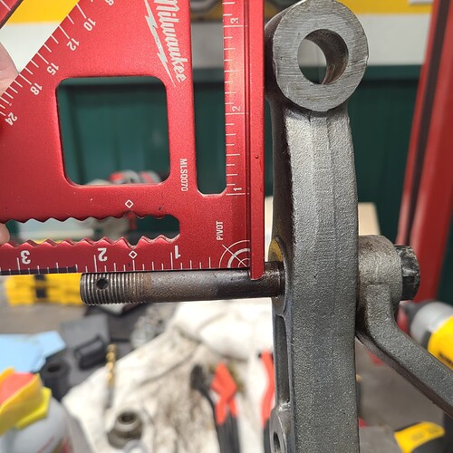
Is it an optical illusion, or is the bolt bent? It doesn’t appear to be perpendicular to the arm.

I see what you mean but I’m pretty sure it’s straight.
One more thing to check tomorrow.

As best as I could, I placed a carpenter’s square against the main arm. The issue is the flats that are machined into the arms so various nuts will sit flush are not all at the same plane so the square “rocked” a bit.
So – OK for me

That’s good, because if it were bent it wouid be even more difficult to extract. I had problems with the equivalent bolt on my Series 2, and had to use a technique similar to the one @BrentKeats described. Good luck - plenty of penetrating oil and the patience to let it do its job should get you there.

Brent has given you a good process I’d add let the penetrating soak a few days or more
Crank the bolt with a breaker bar
Put a nut on the end and tap it hard
Those bolts aren’t cheap may want to save it
Heat the bolt with a weld torch not the lever ( my go to when Finished playing) then crank it
Once it moves you have it
Oh and use a six point socket on the bolt head or you’ll round it
Cheers

Heating the bolt will make it to expand further into the lever: the lever is a forging, so it is OK to heat them. I did that a ton with race car parts, and you can even flame bend a forging without any loss in strength.

. . . and that is exactly what I have been doing. Guess what – haven’t budged it.
Been hitting it with PB Blaster, a 20V hammer drill with the 3/4" socket and I “linked” a 7/8" wrench on the 3/4" for a mini-breaker bar.
Will focus heat (a handheld propane torch) on the lever itself - today.
Thanx

Often just the bolt does it breaks the corrosion and uses less gas . I think the jag manual says not to heat the suspension parts but I understand what your saying
Forged parts

Craig, trying to rotate a stuck bolt due to corrosion, if axial pressing is available to you is the hardest route. If you have a press, do as I suggested in my previous post and you will have success.

With regards to saving the bolt, the only thing special about it is the length of un-threaded section relative to the thread length. It is not an off the shelf item in it’s correct configuration, but a common, garden variety, 4.5" long bolt has the correct length of un-threaded section, but overall, is too long. Simply shorten to the required length and cross drill a 9/64th hole in the correct position for the split pin. A grade 8 bolt will cost you a couple of dollars tops, at a bolt store and a bit of your time.

If you don’t want to go that path, we have lots of them in stock that we have made from the stock item described above. Not having to save the bolt allows you to cut it off near the front, lower lever and therefore, less bolt to have to press through the assembly.

Rgerads,

Brent

1 Like

I’ve had luck doing similar things by putting the part to move in compression with a press and heating around whatever is gripping in it. A heavy C clamp may work as long as the bolt head has clearance to back out once it breaks free (bolt head inside a deep socket). Last time I did it was getting a steering arm off a Healey 100 steering box. It initially resisted but eventually came out.

Brent
OK - I’m a little slow on the uptake at times.

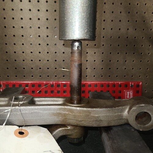
I have now abandoned the vice and breaker bar approach and have loaded the piece thusly in my 20-ton press. Is this the correct approach? See photos

Overview of positioning of piece in press. The press is contacting the threaded portion of the bolt - the bolt head is just barely in view below the arm and ought to drop straight down when it finally releases


,
,
,
Viewing alignment straight on – looks good

,
,

Viewing bolt from the side of the press. In appreciation of @davidxk 's observation, it appears my bolt does have a slight list to one side (or the arm is not laying perfectly flat on the press).
Will the press extract the bolt without damaging the suspension arm?


I will need to replace the bolt(s) - I think this is still the original (I never replaced it until now and I bought the Jag in 1979 with 29,XXX miles on it). The first three threads are boogered at both the start of the thread (not good) and again near the un-threaded shank (not so critical).

So – given the bolt is loss and adding the apparent list/cant, am I better off cutting the bolt (perhaps at the point where the PB Blaster has stained the bolt a darker color?)

Sorry for all the hand-holding questions. I never used a press before except to press out the old bushing on these suspension pieces. The loud BANG at release scares the $h!t outta me. And I don’t wanna damage/destroy the arm ($564) or lever( $374).

(1) So, Brent – I will take you up on your offer of buying 2x replacements for these bolts.

(2) Which reminds me - I sent a PM/e-mail late last week (07 or 08UL22) ordering a pair of your upper wishbones – have you received it?

Let’s talk

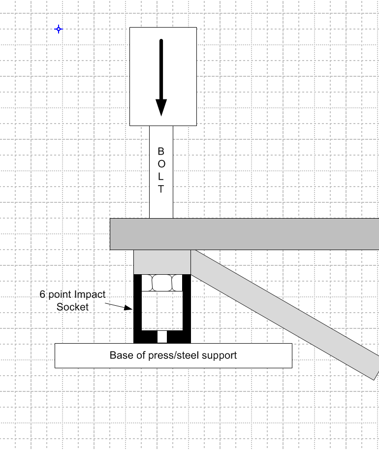
Craig- As previously suggested I would not put the press load through the length of the suspension arm. Use a setup like this:

This way the suspension arm does not see a bending load, just a compression load.

3 Likes

I didn’t understand your guidance vis-à-vis the use of a socket – until now
Your diagram is priceless and explicit. Thanks for taking the time to spell it out,
The scales have fallen from eyes. Even the note to use an impact socket is fantastic – I almost missed it.
THANK YOU AGAIN

Craig
Look good to me, go for it!!!

If you are going to replace the bolt anyway why not reduce its length so less of the shank has to be pushed through the suspension parts. Shortening it will also reduce the “wobble” or tendency to move to one side when you apply pressure.

2 Likes

Sorry a Propane torch is useless and forget the toy tools get a real impact gun or find someone with one . Alternatively use a proper breaker bar you can extend it with a piece off pipe make sure you use a six point socket . If it’s really stuck heat the forging and not the bolt . Pb blaster will help once it moves go both ways back and forth
Anyway you’ve got some ideas. Once it moves it’s easy to get out so personally I don’t know why you’d cut it
Enjoy you’ll get it