I think the OP is now saying that it is 1", and not 15/16". If the split nut can be used to reform the thread backwards (ie by undoing it with some grinding paste) that seems to be the way to go - definitely worth a try no it seems that the shaft thread is not crossed, but simply mushroomed.
They have those as well.
Well Bill, I can tell you this was a simple job until I got into it. It is, after all, just a bit of damaged thread and doesn’t look fatal. Grind the end off on a taper and catch a new thread. We’ve all done it before I’m sure. It’s not brain surgery. But I’ll be danged if it still isn’t getting the best of me. The cut nut and especially with the grinding compound works very well and the threads look great. I’ve ground more taper off the end of the shaft to reveal a good thread. Still no joy. I’ve resorted back to the triangular files. Here’s the setup.

Uploading: IMG_20220606_101809108.jpg…
The wood cross piece is the turning lever. When the vice grip is clamped down, especially with the grinding compound, it can be hard to turn. 50 back and fourths, move it 90 degrees, repeat. Hard on this old back.
The nuts are the same on both output shafts and they both go on the undamaged right side. Like Jim states this shouldn’t take any real special tools. I’ve thought of the interference nut, but it goes on the right side by hand, so I think it’s not. The nut is UNS 1"-16. Others on the EtypeUK site seem to agree with this. The only thing special is the fast threads.
So John, the price on the die is cheap enough right? I’d need it in 1"-16 though, like John says. $33 on Amazon.
Hi Scot…just for info…1in unf 14tpi was a typical thread size.although most charts show 12tpi but 14 is shown as UNS …and UNF depending where you look…1in 14tpi are easy to find as ar cutters etc…used on the output shaft of the salisbury axel on the xk140/150…Steve
If somebody’s pounded on the output shaft enough to mushroom it that badly, if you haven’t already, you should probably take everything apart and inspect the bearings etc.
thanks Steve. It bothers me that you know the XK10/150 used a 1"-14. I swear the 14tpi gauge does not fit on this shaft whereas 16tpi fits nicely. We’ll find out in a few days as I ordered the 1’-16 die.
Measure the shaft with a micrometer and compare the two sounds like it’s a different size something is not right who knows what’s been done . I don’t trust anything is right when problems arise
1 Like
Yeah Bill. I don’t think it was mushroomed by a hammer. I haven’t taken the shafts out because my ring/pinion pattern and runouts look good.
I actually don’t think (anymore) that it is “mushroomed” and you can see the untouched photos at the beginning of this thread. Right now I think this is what is going on.
I talked myself into using the nut off the damaged shaft for my “cut-nut” to use as a die. I think that nut was more damaged than I assessed and I think my squeezing it reformed the threads to that nut. I worried about this when I did it, but not I think that was an error and had I used the “good” nut for the cut-nut, I would not have today’s problem. But then, I told myself, I would not have a good nut to test the thread. The bad nut goes on either shaft, the good nut only on the undamaged side. I could force it I think, but that repeats the poor workmanship a previous person caused. Looking very carefully I can see the problem thread does not look sharp and clean and I believe the good nut is objecting to that.
So, I have ordered the die and will hope it restores the shape.
BTW does anyone know what torque to tighten the output shaft nut to? I checked my manual, but didn’t find it.
1 Like
Scott,
Too bad you’re not any closer to me or I’d have you bring the part here and we would put it in my lathe and cut new threads. I’m near Rochester New York. I’m fortunate to have collected many machine tools in my basement over my engineering career. I have a lot of stuff my offspring will eventually have to deal with. Hopefully I won’t be around to see it.
2 Likes
Get a grinder and cut 3 slots 120 degrees apart into the threads on your split nut. This should allow for swarf to clear more easily.
What you’re doing will work eventually. You could also use a flat file to slightly chamfer the end of the thread so that it gives a lead in for your nut.
Scot - On the older diffs the output shaft assembly pops in and out of the case without affecting any settings in the differential, or the assembly its self. It’s externally shimmed to give the correct settings. The shims are the metal plates between the case and the hub carrying the output shaft. Just return them on reassembly.
Jim, I’ve been using my venier caliper not the mic but I think that’s good enough to distinguish one side from the other. There are differences, but both sides measure like it’s a 1"-16 thread. I can’t remember the good side, but I" measure again and post it.
Wish I was closer too Bill; I’m from Syracuse and go there every few years. The sad thing is my own lathe is in my basement in pieces and my son’s is in Tampa. Coulda shoulda.
Andrew that’s a good idea with the swarf slots…but I think I’ll stop with this bad nut cut-nut. I have used my dremel to chamfer the shaft end so as to make a new 1st thread and then dressed that with my flat file. When the die arrives, I’ll most likely make a sample shaft out of a wood or PVC dowel to assure myself the good nut fits. Slow goes it.
Terry when you first mentioned taking the shaft out, I looked at the drawing and noted that it comes out without losing its setup. That’s plan B.
Nearly the end of this particular saga. My machinist friend was at first pessimistic, but then had success. He had to fiddle with the 4th thread in by removing its top. Apparently this thread is the one primarily buggered by the P.O. With that he set up his lathe for 16 tpi and rotated the cutter head from the inside out; once it seemed to go, it put it on dead slow and let the motor turn it out again. The outer thread was rough so he chamfered the end of the shaft. Once done, he used the die I got to “true” the threads. The nut now goes on easily.
However, in the meantime, I got an excellent replacement shaft from Dick Maury along with two good nuts. With the importance of this output shaft I’m convinced it’s best to use the “perfect” shaft rather than my “repaired” shaft. I also got three 0.003" steel shims from Dick to replace the broken and distorted brass shims; Jaguar did not use brass shims so that is evidence the differential had been opened previously. Like Terry says the bearing housing is where the stack-up of shims occurs and so the shaft can be replaced without affecting the pre-load. I’ll install it with the same shim dimensions but will then verify the end float is zero. I’m using the original Timken bearing. I’ll upload pics when I get to it.
3 Likes
Yes indeed…!
20 chars.
1 Like
With the replacement shaft and nuts, things are moving forward. I have comparison pics of the original shaft (with the damaged threads) and the replacement shaft. The original shaft seems quite worn on its end that goes into the clutch, so it is good I have the replacement. In addition, I’ve inspected the bearings and found the inner bearing to be in good shape, but the outer bearing shows some discoloration and marks where the rollers sat on their outer race - the cup. I’ve ordered 2 new Timken bearing sets from SNGB. While waiting for the bearings, here are pics of the old and new shafts as well as the bearing condition.
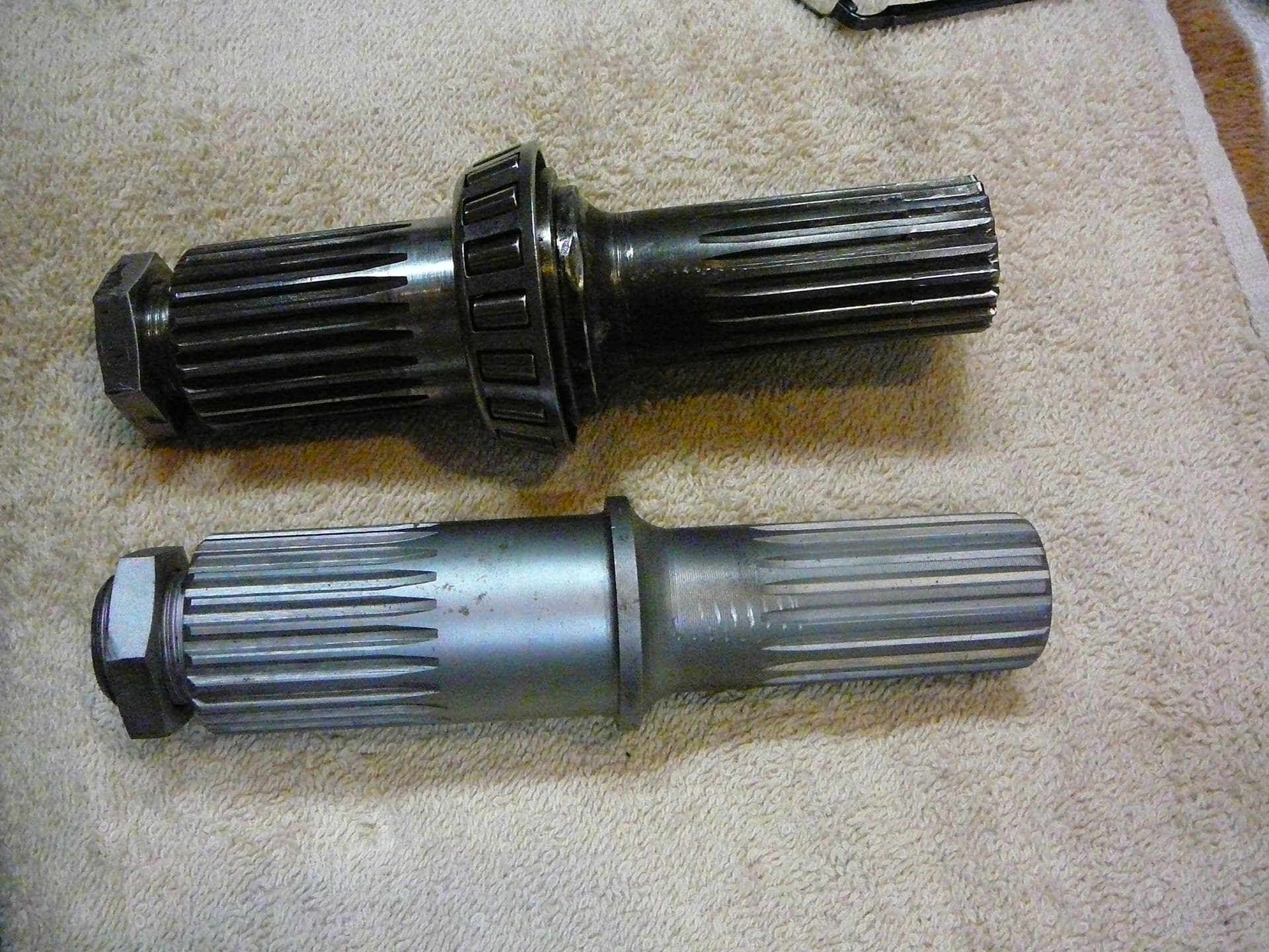


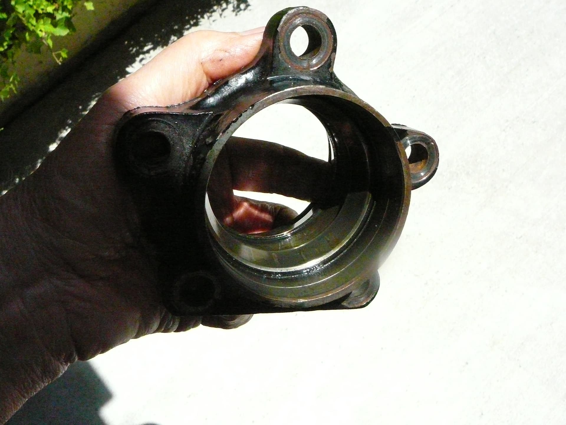
2 Likes
A bit of deviation from the original query on this thread, but I’m now focused on the bearings.
I used the old shaft as a setup tool for a press to install the new bearings. In order to do that easily, I honed the inside of the “bad” bearing so it’ll slide on and off the output shaft. I struggled to find a mandrel that would fit over the shaft while fitting inside the bearing cage so I could press the bearing on the shaft using a press. I’m still looking for a press, but found another friend with a nice shop setup and he had a 12 ton press. You’re going to cringe when you see what I used, but it worked just fine. I first froze the new shaft but left the new bearing at room temperature. With the press setup for the bearing press, I swapped out the old shaft for the new and pressed on the new bearing using a PVC mandrel.


Turns out this friend has a lathe also so we could have made a proper steel mandrel, but I was quite certain the PVC would be sturdy enough to press the bearing on. It was and as a check, we used the steel one to verify the bearing was seated.
I also scrounged up a collection of “mandrels” that would work for the output shaft bearings, the removal of the outer races in the bearing housing and the pressing in of the radius arms bushings.


One more redirection: I decided to replace the bearings on the other output shaft as well even though they looked to be in good shape. Indeed they were Bower bearings whereas the damaged side were SKB bearings. Waiting for the new bearings now.
100% for sure the best mandrel is the old bearing honed out, (with cage removed)
A piece of pipe (or big socket) sits on top
I don’t know where that pic of the brake discs came from … I deleted it.
Thanks Tony. I had honed the inside of the old bearing and now that I have the first side’s inner bearing done, I’ll remove the cage for future use. Good idea! Going to put the outer races in today and then I’ll assemble the left side while I wait for the bearings and O-ring for the right. I’ll use the old bearing when I do the right.
Well you were right Tony. The inner race of the bearing made a perfect mandrel. Simply cut the cage off and find a spacer (pipe) to slip over the shaft’s end. It worked as well my PVC pipe without the worry. I went to my friends shop to use his press for the last time as I broke down and bought one. Air assist to hydraulic, 20 tons. $250. I didn’t want a “jack” style press, but c’est la vie and sometimes we just have to settle to move along.

I’ll get it up and running today…just in time for the new bearings to show up.
I find sockets work for many of these jobs
1 Like