I’ve just replaced the central bearing and all U-joints on my 86 SIII V12 driveshaft, plus the transmission rear mount that was shot, in the hopes to eliminate a faint vibration at 60 km/h and a clunking noise uppon hard acceleration…
Everything is back but the vibration is still there…
As everything is now new, and great care was taken to mark everything, I am suspecting that the problem is the central bearing alignment.
I searched around but didn’t find a conclusive answer, some say to the Left, some to the Right some say make sure the driveshaft is straight using plumb lines or a big straight ruler…
The Haynes manual calls for the special jig but can’t find any dimensions for it and from what I’ve red it only applies for SI and SII cars…?
The Salisbury Diff input is offset towards the Right side of the car.
When I dismantled the driveshaft the central bearing was set almost all the way to the Left, the front part was parallel to the car and the rear part was in an angle.
Even if I set the bearing all the way to the Right the driveshaft is still not straight.
As I don’t have a lift, trail and error is quite difficult.
Any advise ?
Thank you and Season’s greetings to all !
Aristides
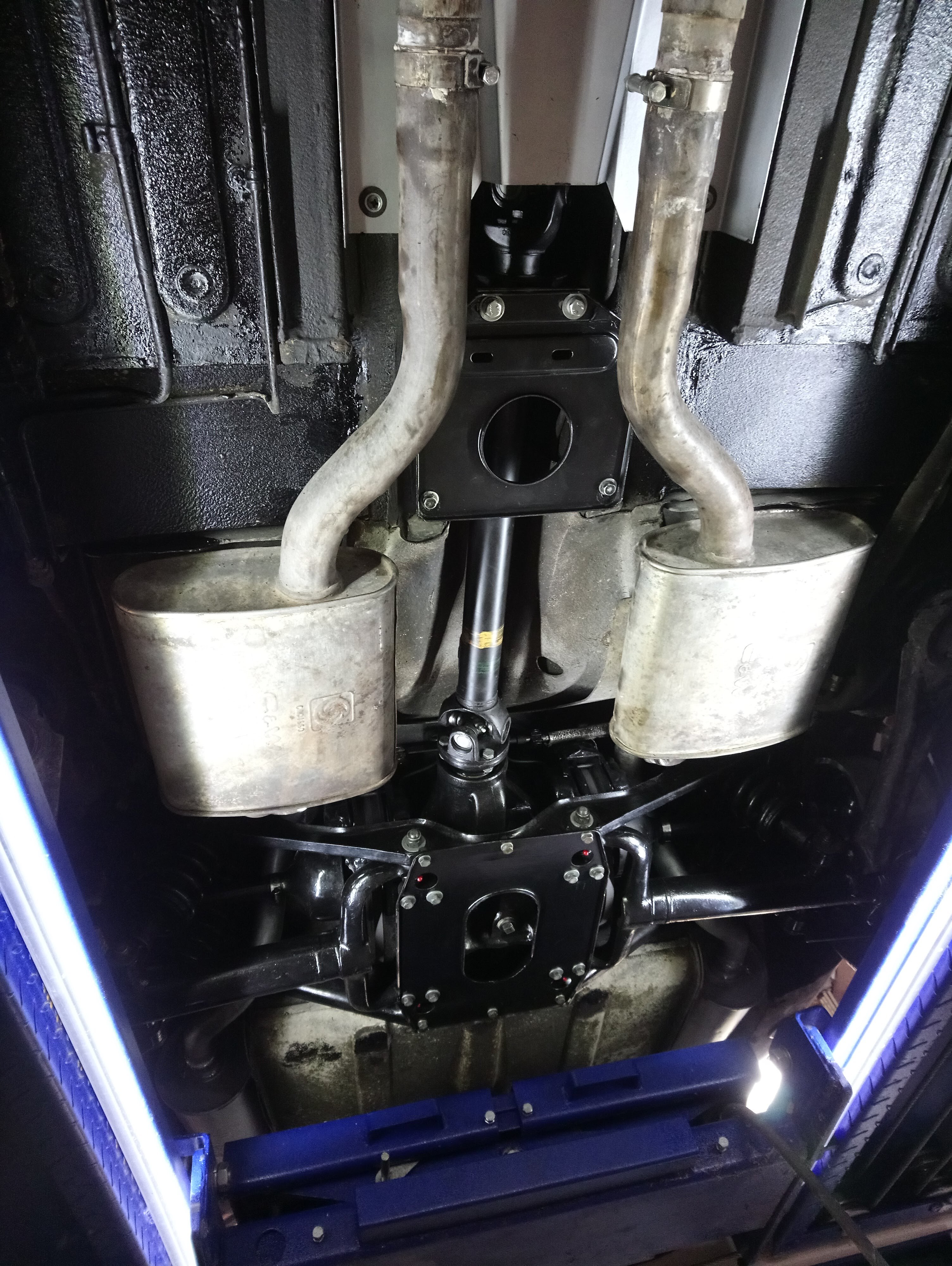
Wow, what a neat and tidy underside. Many cars are not that neat, topside!!
The diveshaft can not be “straight” or can it? The output on the transmission is in the center of the car. The input on the differential is to the right.
So: Emulate a one piece shaft. Cant the center carrier and direct both elements of the shaft on at an angle to the differential. 3 degrees is said to be OK in angularity of the u joints. May not be achieved. or can it?
Or using the center carrier, split the angularity, the front shaft of 1/2 and the rear shaft at the other half.
I’m sure that you have each u joint timed to the other.
My lump dispensed with that “bothersome” carrier. One shaft trans to diff. Must be angular to do that. It works just fine.
So, establishing that straight line by carrier alignment might be the way to go.
All are suggestions, My two piece shaft resides elsewhere with a JL member from the past…
I had a vibration on my ‘92 XJ40 and the only thing that removed it was a replacement driveshaft that I had lying around (as you do)
I would suggest that yours has gone out of balance.
I made something like this up using a 4’ aluminium spirit level as my straight datum. My 72 XJ6 had a vibration in take off which I managed to eliminate following the FSM and using this jig. FWIW. Paul
The worst part is I now have to do this job, and know of a guy that has the Jig, and doesnt have Jags anymore. I tried to talk him into either donating it to the club, or I would buy it, but for some strange reason he declined.
I have to replace a part, not correct a vibration, I will take a lot of measurements beforehand
**
On the S3 there is no vertical alignment, Aristides, the jig pictured by others are for earlier versions.
The standard adjustment procedure is ‘trial and error’ incrementally moving the bearing sideways, ‘leftwards’ is mentioned, and test drive. Resetting to original bearing position by marking after bearing removal may not work? I trust your aligned the universal joints properly - the relative positions of the fixed yokes are important, and are marked to ensure this…
That said; the symptoms persists after parts replacement may imply the parts changed were not the cause? The ‘standard’ symptoms for bearing misalignment is vibration during acceleration rather than being speed related…
The clunking noise during hard acceleration may be caused by metal to metal contact by assemblies twisting? It may be an idea to check clearances between chassis and drivetrain, including exhaust system?
If the faint vibration is confined to 60 km/h it is a harmonic coincidence. Which will be difficult to find, as it is likely a combination of several factors…
And, of course, the V12 should be dead smooth at any speed…
There is no way, at least from my initial checks, even if move the central bearing all the way to the right, to adjust it so that the driveshaft is “straight”.
I wonder if this is also the case for the SI and MKX setup…
I will have access to a lift in a few days so I will check things again and also make sure that the rear transmission mount is aligned properly.
Carl’s thought to have the angles equally divided sounds valid, I think I will give it a try.
I will also make the jig, thank you Tony, and see.
One more as I sip my coffee and munch my buttered sour dough toast…
The shaft is out of “harmonic” balance as frank suggests !! It might have had a small weight welded on to achieve that balance. It might have departed!!
Decades ago my son and I visited an old time hot rod and machinist, Tom Beatty, to have a drive shaft "shortened. He had an ancient long bed lathe. Cut and welded there, then spun fast for balance. No weight needed, but he showed us how he would do that if needed… Weld on a steel washer!!!
I’ve read of using a worm drive hose clamp to test and find the point to add weight… Trial and error as frank mentions…
Well I have the Same thing going on with my S-III thought I’ve got other things to take care of first.
Here’s a snip from the Series III manual (the Green book) and what I’ve discovered is the current series along with the Series I manual make a good manual. The series 1 XJ manual covers the processes in a lot more detail, and in this case, the Series III manual, has the proper parts. this has worked for me. Prop shaft S-1 & S-3 manual.pdf (380.0 KB)
just check the distance between spaces in the tunnel are the same as shown.
did you take any measurements beforehand ?
I use an electronic angle finder to measure driveshaft and pinion angles on 4wd,
they are altered when the vehicle is lifted, and sometimes need to be corrected, as a vibration can be induced
Kirbert
(Author of the Book, former owner of an '83 XJ-S H.E.)
12
Drive shaft theory presumes that the output shaft of the transmission and the input shaft of the diff are parallel. If they are not, there will be vibration. From what I’ve seen on lifted 4x4’s, clearly nobody cares about vibration.
I don’t understand the theory when there are two driveshafts. One simple solution would be for the forward driveshaft to be aligned with the output shaft of the transmission, as though it’s a simple extension of the transmission output shaft, and all displacement between that axis and the diff input would be taken up by the rear driveshaft. That would work in theory, but I dunno if that’s the theory commonly applied in such applications.
Lotsa big trucks have multiple driveshafts. Is there any wisdom to be had there?
**
I’m not sure the propeller shaft should be ‘straight’, Aristides - but the adjustments describes moving the bearing towards the ‘left’ when vibration is encountered…
The engine is fore and aft, and the gearbox output about the centreline - while the pinion shaft is offset, but also fore and aft. So somewhere there must be an angle; either at gearbox/front propeller shaft, or the rear propeller shaft/diff. And the adjustment procedure sort of implies a preference for the front propeller shaft parallel to car centreline…?
And since the vibration was present both before (with the bearing ‘left’) and after your work (with the bearing tried ‘right’); the bearing adjustment is arguably not the issue. Nor were the parts replaced causing it - though changing them were pertinent based on their state…
Frank
xj6 85 Sov Europe (UK/NZ)
**
Kirbert
(Author of the Book, former owner of an '83 XJ-S H.E.)
16
Looking at that diagram of the center bearing support, I see how the bearing is isolated from the chassis by a couple of rubber isolators. But I also see a bolt with a broad head. I expect that bolt is a safety feature, designed to prevent the bearing (and driveshafts!) from falling out on the pavement if the rubber isolators fail. As long as those rubber isolators are in good shape, I presume that broad-headed bolt shouldn’t touch anything. Is that the case?
That’s correct. The plain shank provides the correct depth and the big head provides a failsafe if the isolators let go. As you say - no contact when all operating correctly. Paul
Thanks Mark, it’s exactly what was needed!
It states: Set the central bearing all the way to the right, i.e. make the shaft as “straight” as possible, and if it vibrates move it towards the left.
No, I’ve put the bearing at the same place it was before, towards the left.
I will move it to the right as per the manual.
That’s the case when you have the central bearing towards the left, and that is how it is now in my car.
This is the case for the Range Rover P38:
The front diff input is much lower and with quite an offset from the transfer box output…
Their solution was to have the two U-joints offset as well !!
When I had taken the prop shaft out to change the U-joints I was quite perplexed…
Kirbert
(Author of the Book, former owner of an '83 XJ-S H.E.)
20
Doesn’t matter how offset they are, as long as they are parallel. But when 4x4’s get lifted, often the diff gets rotated so the input shaft is pointing upward toward the transmission. Hence not parallel at all, and presumably generating vibration.