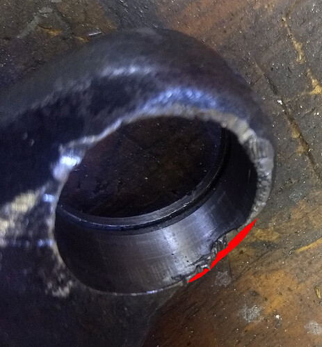
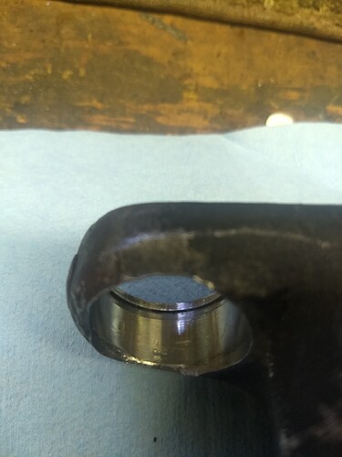
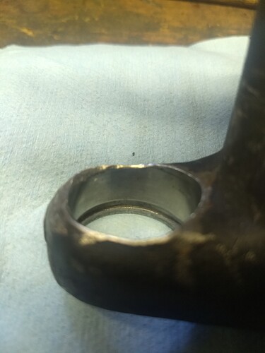
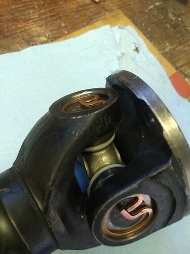
I agree with Kirby that damage is not going to structurally weaken the U/J
I agree with Kirbert and Robin. Seen worse, and still salvageable. Now you can get a die-grinder. (Or a file!)
I’m with Kirbert, Robert and Dave too.
Don’t think there is anything wrong, the damage is minimal.
Try to flatten the edge with a ball hammer first, you will save some material.
File it smooth and you are good to go.
Thanks for the replies, I had assumed I ruined them. I’ve only done ujoints once in my life. Now twice.
I am going to rent a press for the other U-Joint. I do NOT want to push through the ujoint again and be faced with another hack. I used the hammer/socket method on the first one, and it is too easy to tap once too much or too hard.
I have some files, ball hammer, and a Dremel which I will use to smooth things out. Will take several photos of bore to share before I put in new U-Joints.
Ceck out the priceof a press at harbor freight. another 'excuse" to get another toy… Not he best in quality, but will work
Aye, as others said. Just clean it up a bit.
But, aye a drive line shop can cut the weld on a lathe, extract the battered yoke and weld in a new one. They will want to rebalance it!! $$$$
Carl
Just to make sure you’re all looking at the same area, this is the area that I messed up. The red is what is now missing.
The “cup” is still well supported and won’t know the difference. Circlip groove looks fine.
Just make sure that there are no high spots that will interfere with the cup entering the yoke fully.
I’m a member…![]()
A big vise and the appropriate size sockets is all you need Greg.
I think that with a press you will have lesser control over how much you push the caps in or out.
Ok, smoothed out edges of both bores on shaft with file. Hard to tell in photos, but i ran finger inside, nice and smooth. Looks ugly, but they’ll hold?
So long as the cap presses in tightly, it should work fine.
Looks fine Greg.
As for the tool, it’s whatever makes you happier.
Regarding clips…original C clip thickness actually varies! 1.34mm near ends to 1.40mm center point.
New clips are flat on both sides, and measure
Copper 1.36mm
Grey 1.40mm
Green 1.44mm
Ill probably go with grey 1.40mm, but will check for looseness (and tightness) like Kirby said.
Got U-joints in no problem! I see why my tiny error is not so bad, as a good amount of cup isnt even inside the bore.
I ended up using thinnest copper clips. I couldn’t even get both grey ones in. (Positive needle bearings didnt fall over) Once both copper clips were securely in, the ujoint was a bit hard to turn. I gave each yoke a good tap with mallet, and they turn great. Both clips are in very tight.
And although the press helped, i eventually found the two socket method better. For more precision, just used smaller hammer.
Thanks all, ill double check my work in morning, and then put driveshaft back in.
A sanity check I always did: go around the inside of the clips, using a pin punch and a light ball pein hammer, to ensure the clips are fully seated in their grooves.
Thanks, will do.
I’m curious, a lot of you have engineering backgrounds and know-how. I’m just a grease monkey.
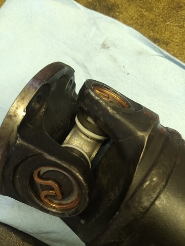
The driveshaft - with all that torque where is the stress on the ujoint? I assume the cross takes most of it. How much is on the cups and needle bearings and yoke and bolts holding the flange? I notice those 4 bolts aren’t even grade8.
Interesting questions, Greg! I’ll answer best as I can…
-Cups/needles: all the force is communicated through them, and through the cross.
-Yhe bolts through the yokes are very short and fat, and because of the clamping force they exert, Gr.5 bolts are plenty.
Now, @Mike_S, what say you, from an Engineer’s POV?
The cross takes all of it! Torque comes in through the cups on one axis, passes through the cross, goes out through the cups on the other axis. Hence, the cups also take all of it.
The bolts might not be Grade 8, but they should be a close tolerance shoulder type. The torque is applied to those bolts as shear, right at the joint between flanges. Some claim the fiction of the faces of the flanges takes some of the torque, and it certainly might in practice, but the designer needs to presume that all these parts are lubed (by an oil leak from the V12) and that 100% of the torque is divided among those four bolts. They should fit snugly in the holes, and the threads should not extend close enough to the heads to get to the joint between flanges.
You can find that answer in several places, a AISC steel construction manual, numerous SAE white papers, Machinery’s Handbook, etc, but the physics works like this.
Hypothetical: you have an empty one cubic foot (12x12x12) box sitting on a smooth steel plate.
For this example, assume the box is weightless, the content of the box is subject to Earth’s gravity and the static coefficient of friction between the box and the plate is 0.100 (very slick).
If you filled the box with 150 lbs of concrete, it would take 15 lbs of force to get the box to slide from rest.
If you filled it with 500 lbs of cast iron, it would take 50 lbs to overcome the static friction and begin to move the box.
How does this relate to threaded fasteners? In a bolted joint, the threaded fastener replaces gravity. How much axial force is applied to a connection by a 5/16" cap screw? If you are calculating the allowable tensile, or axial, load on a fastener, you use the diameter of the thread root, not the shank diameter. Say that is 90‰ of the shank, so 0.281", and the cross section is 0.0621in^2. If you have a bolt with an allowable stress of 70,000psi, (roughly SAE Grade 5) then 70,000lbs/in^2 x 0.0621in^2 = 4,349 lbs. If there are 4 bolts, then the force is 17,400 lbs and the friction keeping the two parts from sliding against each other (assuming the same 0.100 coefficient of friction as above) would require 1,740 lbs of force before you get into shear on the cap screws. Note that this is only valid so long as the bolts are axially pre loaded (torqued) to the allowable working value. If they are loose, not only do you loose the frictional force, you also introduce combined forces of shear and bending on the fastener. These combined forces will exceed the design stress allowance, and the cap screws will fatigue and fracture. I’m looking at you, Salisbury 4ha ring gear bolts.
