Thanks for the information and advice, and yes, I have the proper crimper for the kind of terminal you show.
The harm with soldering in that case, would be that you will likely get wicking of solder between the wire strands resulting in a stiff easily fractured area.
No value, same harm. Have you EVER seen a production car with ANY soldered terminals on its harness? There’s a reason for that. Soldering makes the wire MORE likely to break at the solder boundary.
Yes… harmful.
DO NOT solder.
I have reason to believe Jaguar soldered some wires on the E-type harness, at least for a time. I would think soldering is much too time expensive for economical production, but this was in an era when labor was relatively cheap.
This terminal fitted inside the alternator F+/F- wiring plug. It looks like it’s factory original. I assume that the material fusing the broken strands is solder. What should be the crimping ring was not crushed at all, so it never appeared to be the main source of strength for securing the wire.
I admit I re-soldered this connection, because I wanted to keep the original plug and didn’t know if I could get a different terminal to fit in the plastic connector plug. It may fail like the previous one, but I doubt I’ll be around to see it. And if I am, I’ll know where it is…
Dave
I believe a soldered connection is superior for conductivity and probably used in this particular application for the higher amp rating.
Frankly, I never paid that much attention to it on a new car. Anyway, every terminal end seems to be tucked inside some kind of plastic device to lock into it’s counterpart so pretty much concealed from view.
EDIT: And thanks everybody for your responses.
Have you EVER seen a production car with ANY soldered terminals on its harness?
That depends on what you consider 'production, but my 64 Porsche uses factory soldered bullet connectors throughout.
Work ok for you?
Cheers
D
I have these too and it looks like they are welded. It’s not solder.
A properly crimped connection is better but I think soldering is good enough. I don’t think soldering is any help in current capacity.
Regarding soldering vs. crimping, I just posted this in another thread:
After starting up my 67 OTS from winter mothballing, no issues. I get to the hardware store and come back out to the car and get a single “click” when trying to start it. I’m thinking, battery connection. I had a screwdriver, so I loosened the ground helmet connector, wiggled it around, and retightened. “Click” and then nothing. Did this a couple of times and to the positive helmet, too. I thought, bad battery. So a guy from the hardware store has jumpers and we get the car going to high idle with choke. He removes the cables, and the car is fine until the idle drops, and then dead. Rinse, repeat, same problem. I’m confounded and get AAA to haul me home.
In my garage, I test the battery. It’s fine, so it obviously has to be a cable connection, but they are both fine. Finally, I pulled the negative cable and wiggled the helmet connector and it pulled off in my hand! On inspection, it is a soldered connection that came loose. This was a true WTF? moment. I crimped the connection, and still no luck, so I checked both ends of both plus and minus cables. All four of the soldered connections had come loose over winter storage!
Crimping all four ends fixed the mystery. Quite obviously the car worked fine in the parking lot when the alternator took over from the battery at high idle, but the engine died when the battery couldn’t supply spark at low RPM.
This is one of those completely stupid moments where old cars with old components just tell you it’s time to give some attention. And all it took was some vicegrips
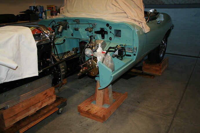
Yes. As I recall, threading the driver side engine frame into position was a little difficult due to the steering column, but I was able to do it. This approach has the advantage that you never need to use an engine crane - just a trolley jack, jack stands, and a dolley to roll the engine out on.
That makes sense … I’ll feed mine in later when I attach the rack.
D
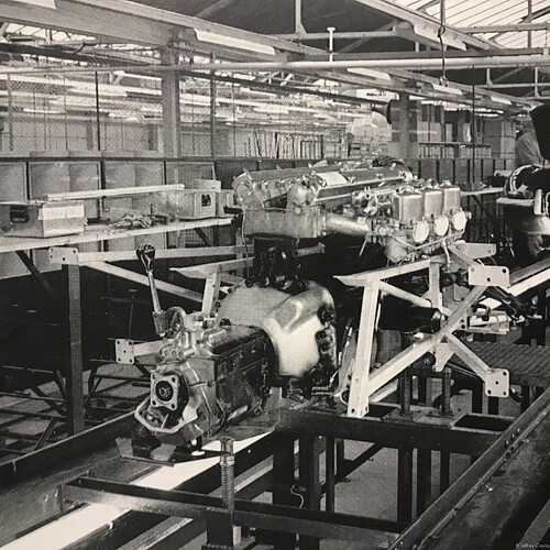
I was reading Porter’s E Type Definitive History book yesterday and learned something further on this. It turns out Jaguar only did the assembly this way for a short time, and then switched back to keeping the sub-frame on the car and installing the engine from the top later. In an interview with a couple assembly line workers, one worker said:
“Initially we put the sub-frame on to the engine, and then banged the lot into the car and bolted up to the bulkhead. You’d never get away with it today, but those bolts used to go in like six inch nails. They’d ‘welly’ them in and the half of them would strip and God knows what. They used to have to spring the sub-frames to make them fit - if you’d seen how they fitted them, it was amazing!”
Sounds like it seemed like a good idea initially but found it was too much and a poor way of fitting, and switched back to how we see it being done today.
Found a picture of an engine fitted to the sub-frame during the short time they were built that way:
Note the trans mount: that’s what Tweety had, and nobody has explained to my satisfaction why they abandoned that, and went to the Pogo spring!
Also, Tweety’s mounts were OE, and in fine shape.
And the shift knob is in place too, assuming for the photo op…
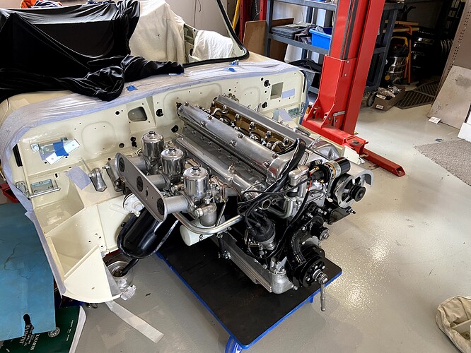
My intention is to place the motor in position held by crane and supported underneath with a small lift whilst the level can be fine adjusted …the front is on the hoist the back on its wheels… with it in place will reattach the frame which I removed as a whole assembly … this is the way a few restorers do it here.
I’ll let you all know how it goes!..here’s a picture of it placed where it will be placed
Cheers
Danny


