Mark V Wiring Harness

Just recording for posterity some observations about the wiring harnesses for Mark V.
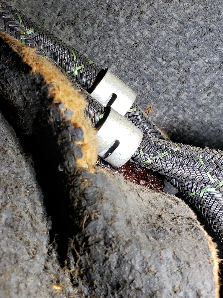
Previous models have the main wiring harness from the firewall (scuttle) to the trunk (boot) running along under the chassis frame, and held on by a number of clips. It is fairly easy to install, but is exposed to weather.

So for Mark V they decided to run the harness through the door sill. I believe this was the first model where they had a boxed-in steel structure as the sill. Anyway it would be protected from weather in there.

The installation is really two problems, the door sill and the dogleg.

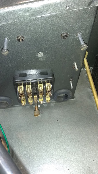
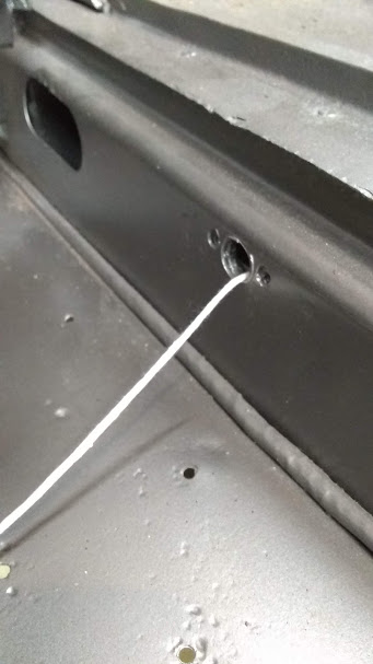
The factory installers either left a piece of string or wire in there as the body was built, to pull the harness through later, or maybe had a 6 foot (2 m) long stiff wire with a hook. They probably did it after paint but before the fenders (wings) were on. There are a couple of restrictions on a saloon, one on a DHC, the boxed in door opening stops. The harness has to pass those. Also a short stub wire has to be pulled out at the switch hole in the door sill, so there must have been a second wire or string from the front through the switch hole.

The new harness has a number of individual wires hanging out of the cloth wrapping in places, and exiting the wrap pointing to the rear, the pulling direction. From years of watching pro electricians pulling wires through conduits at my lab, I learned the trick of bundling wires together with tape. Also there are some rubber covered bullet connectors on the harness, which I removed so they would not fall off inside the sill. In one place there are seven bullet ends together, so you want to wrap those with tape, and don’t fold them back, wrap them in the pulling direction with the other bundle, so they will go up the dogleg.

I tried 4 times to push my harness through from the front, no luck, it bunched up inside. So I got a piece of stiff wire through from the front, and it was easy to get it out the back end which is somewhat open. Hooked the harness to this wire and pulled it in. Places where a large bundle is passing the door stop boxes, you just work it back and forth until it goes through.

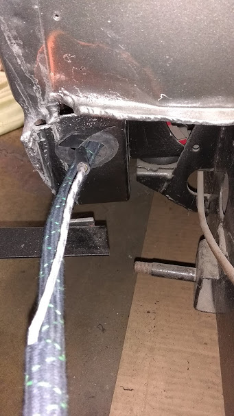
At the dogleg, the harness turns up and fits through a place where the inner fender and sill meet, then up past two caged nuts that hold the rear wing on. Here is where the 7 bullet ends get stuck on the caged nuts, so keep that bundle on the inboard side and the smaller bundle outboard. There should be a plastic sleeve on the harness, that ends up at this dogleg, to protect the harness from the weather and road dirt there. You want to get the end of the sleeve up into the body at least to the floor level.

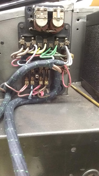
The saloon harness then splits where one longer tail runs up and across to the rear of the sunroof where there are clips for it, and over to the left rear interior light. DHC is similar but runs along below the convertible top. There are wires that feed off to the trafficators in the saloon center posts or DHC sides if you have them. If your car is a USA delivery and doesn’t have trafficators, these wires are not used and should be protected so as not to touch the body. The shorter tail has connectors for the trunk harness.

2 Likes

The SS Jaguar system is crazy running externally. The Mk4 system is much more sensible and runs through the near side chassis leg. The underslung frame is quite simple to feed the loom through because it’s straight end to end.

Peter

Yes, that wire bundle and the fuel pipe also running along there on the bottom of the SS chassis makes it hard to find a place to put a jack and jack stand.

For the Mark V, you want to make the firewall (scuttle) connections before you pull the harness too far into the sill and have to pull it back.
I forgot to mention the door switch wire is a separate wire from the main harness, and you need to pull that first. Then when you pull the main harness you connect them as you go.

Some progress today.

I put short 16 gauge wires green and black with bullet ends on the wiper motor before attaching it. This motor is not polarity sensitive, in that I don’t think we care which way it turns, it still cranks the shaft in and out.


The panels inside must be attached first because the front screws are hidden by the fuse box and voltage regulator. The top screws cause a distortion in the top of the scuttle which I tried so hard to get nice before painting. :frowning_face:

There are 4-tapped-hole plates inside to mount the fuse box, terminal block and voltage regulator. Put these on loose with all four screws, then tighten the two middle screws before you pull out the other two.

Then you can attach the terminal block and fuse box.

I learned that you should start with the fuse box, terminal block, and voltage regulator (control box) and work from there. Otherwise you find you have to rotate the harness that you already pulled through the door sill and dog leg.


The dash/engine/body harness goes through the outboard hole. The dash/engine/headlight harness goes through the inboard hole. In some places where they branch they are a tight pull through the grommets.

I stared with the dash/engine/headlight harness.
Leave the regulator off, wire the fuse box first, then the terminal block, then the regulator, then attach the regulator to the firewall (scuttle).


I left all un-terminated wires the length as sent, just stripping back 1/4" (6mm). I wanted to see how they all fit before deciding if any could or should be shortened. My old original wiring was neater than this, so the factory installer must have known how much to cut back each one.

I found the order of the wires coming out of the harness bundle and going into the terminal block was different from the instructions, but it doesn’t matter as long as you are consistent and get the right color wires connected.

2 Likes

More progress today.
I shortened and re-stripped most of the wires going to the fuse box, terminal block and voltage regulator.
Also found that I had to pre-bend the bundled harnesses and work them around a lot to get them to pack into that small space.


The 10 gauge brown wires (2) and a 14 gauge all to terminal 4 of the fuse box were the worst, too many wires fitting into one terminal.

And then you have to push them all back in there to get the fuse box cover to fit.

I can understand why the factory did this work with the body on a trolley, not on the chassis.

Anybody ever seen a cable clip like this, kind of like a saddle?


It fits a cable bundle about 5/8" diameter and hooks into a hole behind the battery.
This one has lost a stirrup, like it was for a cowboy with one foot.
Near as I can guess, it is C.2729 Clip, Securing Panel Cables to Interior of Scuttle on page 91A of the SPC.
Do these have a trade name?

Here’s a better picture.


I found a couple more smaller ones on the old wiring, so this is definitely original to my car.

I’m not sure but something here looks similar although it might take a lot of searching:https://www.alibaba.com/countrysearch/CN/spring-steel-clips.html

I got there with a Google Image Search:1950s circular Spring Steel Wiring Chassis Clip

The crest looks like Sheng or Shong.

Hi Rob, in the photos below is an image which shows two of these clips on my driver, please confirm. These are behind the battery on the right hand side and inside the car.

The next photo shows some clips which differ, with three of them on the right hand side and one on the left (not shown).

If you can let me know what supply you need, my parts car is likely to have such clips still in there but perhaps with more patina than my driver car photos show.

Yes, that’s them in your first picture, behind the battery and on the inside. Thanks for the confirmation. I’m still digging through boxes to see if I have any more, I found a bag of omega clips.
The P-clips in your second picture are well known and carried by Moss Motors and others. Thanks for the confirmation of their location inside on the right hand side. My notes have wiring routing and holes identified for clips, but not which type of clip in each hole.
Thanks Peter for the source in China, unfortunately I don’t need 10,000 of them. That’s probably where Moss gets them, but this big saddle is not used on the XK series, nor on Mark VII or Mk2, so not on their priority list.

What a wonderful assortment of clips! I wonder what the bronze coloured one, which resembles a section of a Lotus tuber, might be used for?

Tim

Rob,
Do you know where I can get a regulator cover? Mine is missing a couple pieces!

Here you go!

Best wishes,

Tim

1 Like

Thanks Tim, I’ll order one from them today.

Wayne

Hi Wayne, re your regulator cover, mine was missing larger parts of the cover then shown and I was able to repair the cover with body filler and a bit of sanding then emery work, then a respray, just like original and happy with the result.

When I bought my car 27 years ago the control box I got with it had a complete mounting lug missing and as Jeffrey did I used car filler to mould a replacement that served me well until I found a better one.

Peter

1 Like

Thanks guys. I’ll give that a try. I suppose I could always make a mold and pour one out of epoxy.

Hi Rob, here is a photo of two clips pulled from my parts car. The clips were held holes through the firewall by the two tabs on each. Compressing the tabs towards hole center and pushing through the firewall from the battery side freed them. The method I used was to have one tip of needle nose plier above a tab and pushing tab sideways and downward via a screwdriver handle pushing sideways on plier. When the tab was able to pass through the hole, I tipped the plier so the other tip (over the hole and not pushing the tab down) could push tab into the hole and press the tab through.

Dost thou covet one or two of these trinkets?

More progress today.
We have learned from the XK forum and Grace’s Guide that the saddle wiring clip was made by Carr Fastener Co. of Stapleford Nottingham and used the trade mark Dot. They made other clips used on Mark V brake and fuel piping.


I fixed the one broken clip by welding on a new tab, smallest weld I ever made.

Did all the instrument panel connections today.

Made a peculiar discovery.
The grounding terminal on the instrument panel is a grub screw type. The black wire on the new main body harness which grounds the instrument panel had a ring terminal on it. Not compatible. At first I thought it was a mistake in the new harness. So I checked the original body harness; it also has a ring terminal. Then I found the separate original harness to the map and panel lights has a black ground also with a ring terminal. Main body and map light harnesses and instrument panel all original to the car, but it’s a mystery, where was this ground originally attached?

Dug out the old photos. Photo of the old wiring shows it, the red arrow; both wires were attached to the speedo, one of the screws that hold the inside mechanism to the speedo case!!??


I can’t believe they would disturb that screw on the speedo.
Why didn’t they use the grub screw terminal, green arrow?
Or better yet, use a screw and nut there for attaching a ground?
I think that’s what I’ll do.

1 Like

Thanks Roger. I’m set for now, but hang on to them. I’m working forward and back from the instrument panel now, so we’ll see what new problems I run into.