Project updates related to 'Delayed Hot Start' topic

Figured I’d break a topic off for those interested in the stuff that originated in the Delayed hot start issue.

I’m in week 2 now of a 10 week sprint (yes, for those software geeks out there, I have this project mapped out in JIRA).

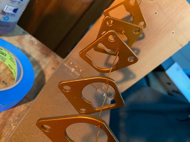
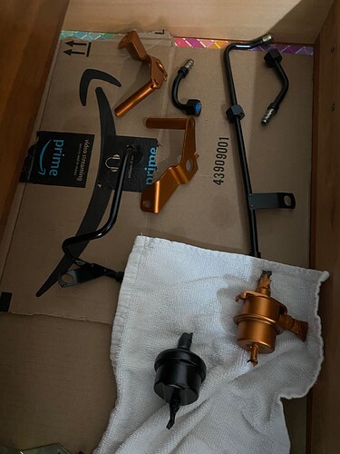
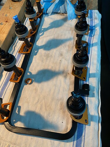
I’ve got most of the engine compartment tear-downs done - feed and return lines out, fuel rail out, air pipe out, etc. I’m in the process of prepping and painting the various bits that I want to cleanup. I’m just about done removing all the old fabric wire loom wrap that is just disintegrating all over the place.

I knew that the oil pressure sender was leaking and it looks to have been so for a looooong time - I found what I think is the copper washer sitting under some wires at the back of the engine that is supposed to go on it, but I’ll know for sure once I rip the old one out. Also, new discovery and additional scope creep, at least one of the banjo bolts was seeping oil - so I got new ones coming from @John_John1.

I’m hoping to have the engine cleanup done and some reassembly started, but main focus will be on removing the old, broken injector connectors and starting the process of wiring the new ones in.

Question - I am planning on just removing the connectors and reusing the original wiring which is in really good shape. Should I use solder when connecting the two wires to the little connector bits?

I’ll post again in a couple of days and once I get this project done, we’ll get back to seeing if all this does anything for the ‘Delayed hat start issue’ - although indeterminate as to what fix actually resolved the problem outside of “Just fix everything” :slight_smile:

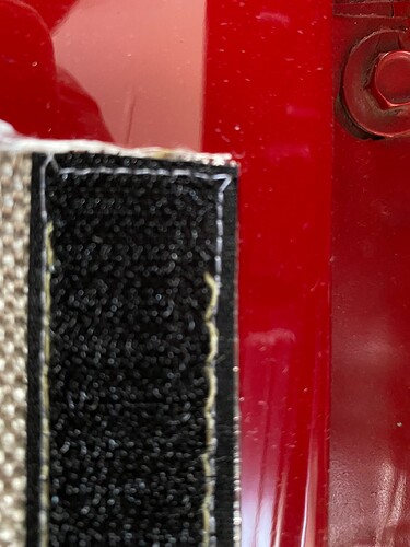
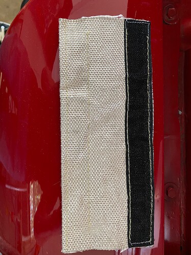
Also of note - see the last couple of pictures on some stitching had I my older daughter try. The quick connect sleeves look to have good material, but the stitching is horrible! Makes the product totally useless for more than one use as the velcro just pulls off the protective material. When you cut the pieces to fit the stitching just starts to unravel. If you try to use a lighter to seal the threads, it melts the velcro :frowning: On the bright side - it took my daughter 30 seconds to restitch that piece, it’s tight, and I can use whatever color thread I want!

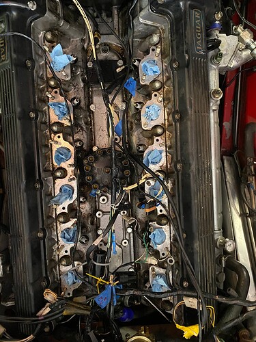
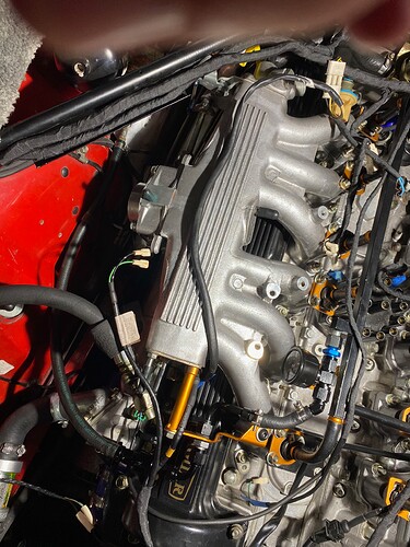
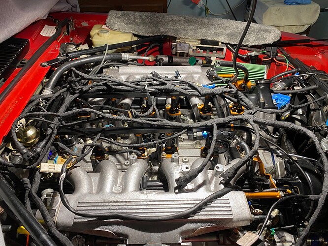
I particularly like this pic of the engine from above - I plan on taking other ones from this same angle as things progress…

Old thread is yellow - new stitching is white…

2 Likes

Is that material a “tube sock” of insulation, for the fuel rail, that is secured with the velcro - keep coming with the pictures and explanations as it sure helps - thank, Tex.

I do too, but it’s always a big debate…
This is what my aerospace electrical engineer cousin recently told me:
The safest is crimp and solder, so you have both a mechanical and chemical bond, but this applies only for static applications.
For automotive applications though, where things tend to move around and vibrate, soldering is not that optimal, in theory at least.
The reason being that the solder travels up in the wire making it hard and introducing a hard transition point from hard to elastic above the clamp, and therefore a stress point, that could eventually brake the cable.
This is why all automotive connections are only crimped.

Aristides Is correct about solder not being ideal in the automotive environment because of the hard transition and the potential for breakage. I still recommend soldering, however I always reinforce the soldered connection with heat shrink that extends beyond the hard transition points.

3 Likes

Even if you cannot reinforce the wire near the solder joint, in my experience more electrical faults are caused by corroded crimped connections than by wires fatiguing near solder joints. Wires in cars just don’t move around that much.

1 Like

I think the shrink wrap helps the soldered junction from movement.
I wouldn’t think a very small dab of black permatex inside the ends of shrink wrap before heating would hurt either.

I went ahead and pulled the intake manifolds. New gaskets on the way. When removing, most of the nuts weren’t super hard to get off. I had sprayed with WD40 to start loosening up some old grease and crud as I was cleaning the V. When I pulled the manifolds, the WD40 had saturated through the cardboard gaskets which makes me think they weren’t on there very tight - in other words, the gaskets themselves were dry, but WD40 had made it’s way between the manifolds and gaskets.

In any case, not gonna be a problem now.

Paint work is coming along.

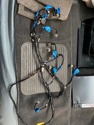
Injector wiring harness is out and getting ready to get new connectors.

And now the pics…

1 Like

or liquid tape… twenty characters

Alright… so, it’s been a while since I was able to make any progress, but here goes on hopefully the useful bits. (Really, who cares if I finished wrapping the injector loom? how did I do it and anything useful from that :grin:)

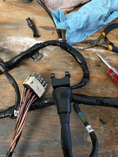
  1. The EV1 connectors turned out to be not so bad. I was able to pop the two wires and connectors from the crumbling connectors on all the injector connections and the ones to the various other sensors. All the little connector bits and wires look great, so I was able to just pop on new connectors and shrink wrap. Key to adding the new connector was to make sure the tabs on the wires were slightly out. When you press the new connector on, you can hear two faint clicks, one for each wire - the inside of the connector has a little ledge that prevents that wire from coming out, but only if the little tab is out and pops into place.
  2. I used Tesa tape to wrap just about all the wires. Key here was to use fresh tape on the easy to get to things and then as the roll gets small, stop and save that small roll for the hard to access areas.
  3. I used Wirefly shrink tubes on the EV1 connectors. I used the rubber boots that came with the connectors on the injector connections, but I may go back through and just use the shrink tubes that are much higher quality than the rubber boots that came with the kit. I used two different size tubes - 3/8" and then a 3/4" on top over the connector. The key here is getting the 3/4" tubing to shrink nicely onto the connector. I found two methods that worked well - first was to push the shrink tube towards the connector as I was heat shrinking it. The other method was to shrink onto the connector first, let it cool, then shrink the bottom part down to the wire.
  4. Sump tank is in pretty good shape. There was some sludge in the bottom. Filter was clean, but the seams were open in parts, so I wonder if all the sludge might have just been passing through the holes in the filter instead of collecting there. There was a little rust inside the sump tank, so I went to Por15 route - cleaner/degreaser, metal prep, and fuel tank sealer. You might be tempted to get the motorcycle collection which is small versions of the stuff, but you can actually price the 3 things out individually for cheaper - I ended up with the gallon of degreaser, 32oz of metal prep and 8oz fuel sealant.
  5. Have the cut-off valve and 100 micron filter in place and mounted int he trunk, just waiting for the sump tank sealant to cure. I went with AN6 adapters to make the turns instead of fuel hose. Using push-connects where rubber meets to metal, so to speak :slight_smile:
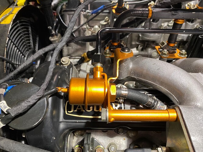
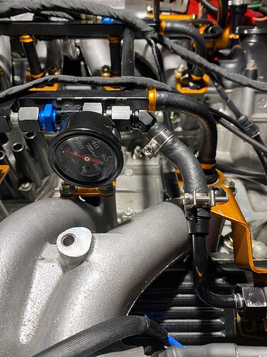
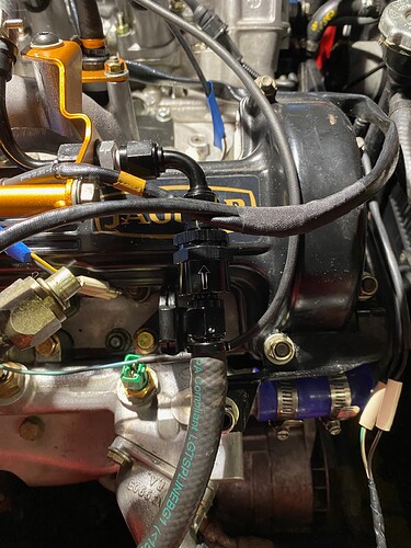
  6. New FPR on the B-bank and fuel pressure gauge and check value right in the area where the FPR-A was located. At some point, I’m going to move to using in cockpit gauges, well really, on phone or tablet gauges, but that’s still being researched and this was a simple start. Of absolutely no use while driving of course, but still, it’s there and future project will be much easier. The check-valve will be key as many have said this greatly impacted hot-start issues.
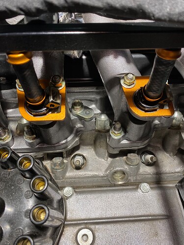
  7. Remove the exhaust air pipe and plugged the holes using the original brackets, ball-bears, and black ATV - I think I documented this in another thread…
  8. Ohh… almost forgot and it’s important for a question I have :slight_smile: I removed the AAV and fabricated a cover plate using 3mm (or maybe it was 4mm) aluminum billet from McMaster-Carr (where just about all my replacement bolts, nuts, and such come from if any cares). Not hard at all using just a grinder and sander.

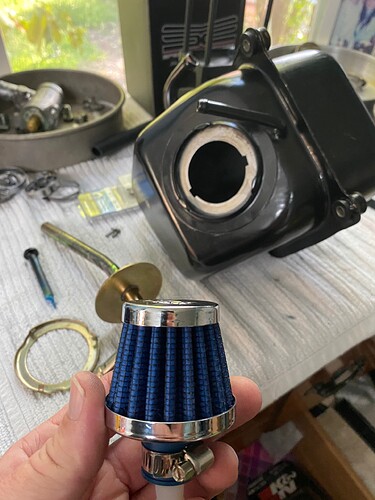
Before the pictures, I did have one question… I’m going to service the distributor and reroute the vacuum hoses. On the base of the distributor there’s a vacuum connector on each side - does it matter which side pull sin the ‘fresh’ air and which side does the sucking? This was one thing I didn’t get a good picture of when I was disassembling everything. Turns out, interesting thing here, is that a simple crankcase breather filter connects really easily to the vacuum hose and looks like it’ll do the trick instead of the lawn mower filter.

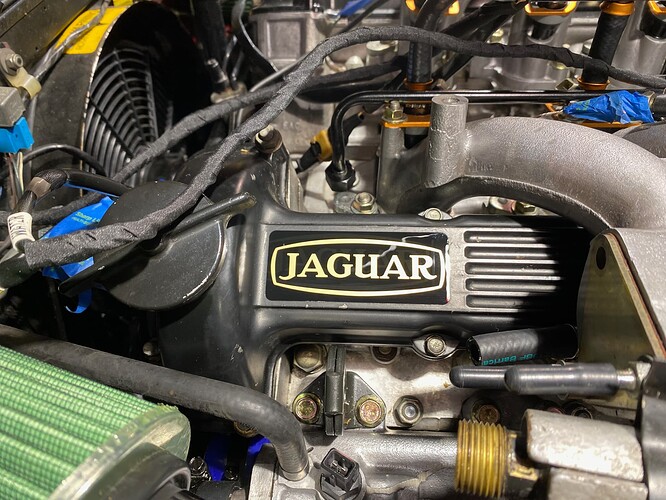
New sticker!!!

there is such a thing as liquid electric tape.

i prefer solder.

Just fixed an extension cord. I whacked it in two while hedge triming. well, actually weed whacking with a hedge trmmer!!1

Stripping back was the hardest part of the task. Next was keeping the shrink tubing away from the solder heat and shrionkig befre I wanted now. soldered, shrink tubed and wrapped in tape. And, it works got to play with my tools Solder stuff and heat gun and utility kinfe and wire stripper.

FYI - answer my own distributor question… Quite obvious once you take the cap off - doesn’t matter.

Wow this project brings back memories! Looking great! Love the details.

Great job on the project!

Tesa tape…

If you don’t mind my chiming in…

I’m a big fan of Tesa tape but, truthfully, I’d suggest something else for the injector harness and anything subject to that much engine heat. In a couple years all that tape will be a million little fabric shards sitting at the bottom of the Vee.

Ask me how I know ! :slight_smile:

I say “couple years” as a guess. That’s about how long it lasted on my V12, which is a daily driver, before it began disintegrating.

YMMV as to longevity

Cheers
DD

From what I see on Amazon, there are now two types of Tesa tape, interior, and high heat. The high heat is rated to 150 C. The listing says its their “newest” tape.

Tesa’s Most Advanced High Heat Harness Tape 51036 Mercedes, BMW, Audi, VW https://a.co/d/iSrg5Mw

1 Like

Most modern harnesses (and some British vintage ones) are wrapped in non-adhesive tape, and are glued only at the ends. This allows more flexibility and doesn’t turn to a gooey mess. If it’s good enough for a Toyota, it’s good enough for me. My .02

Yup - used the high temp Tesa. And if you notice I’m laying out the harness and other wiring around the fuel rail. After testing that I don’t have any fuel leaks, the rail and wires will all get wrapped with that heat shielding stuff that my daughter is fabricating for custom fit and nice stitching…

I found that cleaning the engine V from all that old tape and thread worked really well with a heavy duty air compressor… Makes a mess on the floor, but :man_shrugging: whatcha gonna do :grin:

I’d like to add, what I sometimes get on a hot start is a ping or two just as it catches. The cylinders must be so hot, that the fuel is pre-igniting? Or is this the hot fuel? I’d say I only get about 1-2 pings, and then it idles a bit low for 10-15 seconds and then runs fine.

I assume this pre-detonation is not harmful?

Yes, heat soaked cylinders in combination with very lean fuel mixture as very little fuel exits the injectors.
A few pings do no harm at all, it’s the prolonged pre-detonation at WOT that melts the pistons.

Thanks, glad it’s not harmful.

I wonder then, is it not vaporized fuel in the rail causing hot start issues, but vaporized fuel in the injectors? Would the plastic surrounding of the injector absorb more heat? Maybe putting heat reflectors underneath the injectors would help? Or is the fuel in the injector emptied in an instant? OR does the injector need cooling, because it is vaporizing the fuel as it passes?

I thought earlier in this thread someone hypothesized that it was the fuel in the short injector hoses vaporizing. Flushing the rail doesn’t help, cool fuel just passes over the top…?