RobY / '68 S1.5 OTS resurrection - Part 2

Following @Wiggles lead, I’m going to start breaking this thread up into smaller pieces. I probably should have started doing that sooner. So, here’s the start of Part 2.

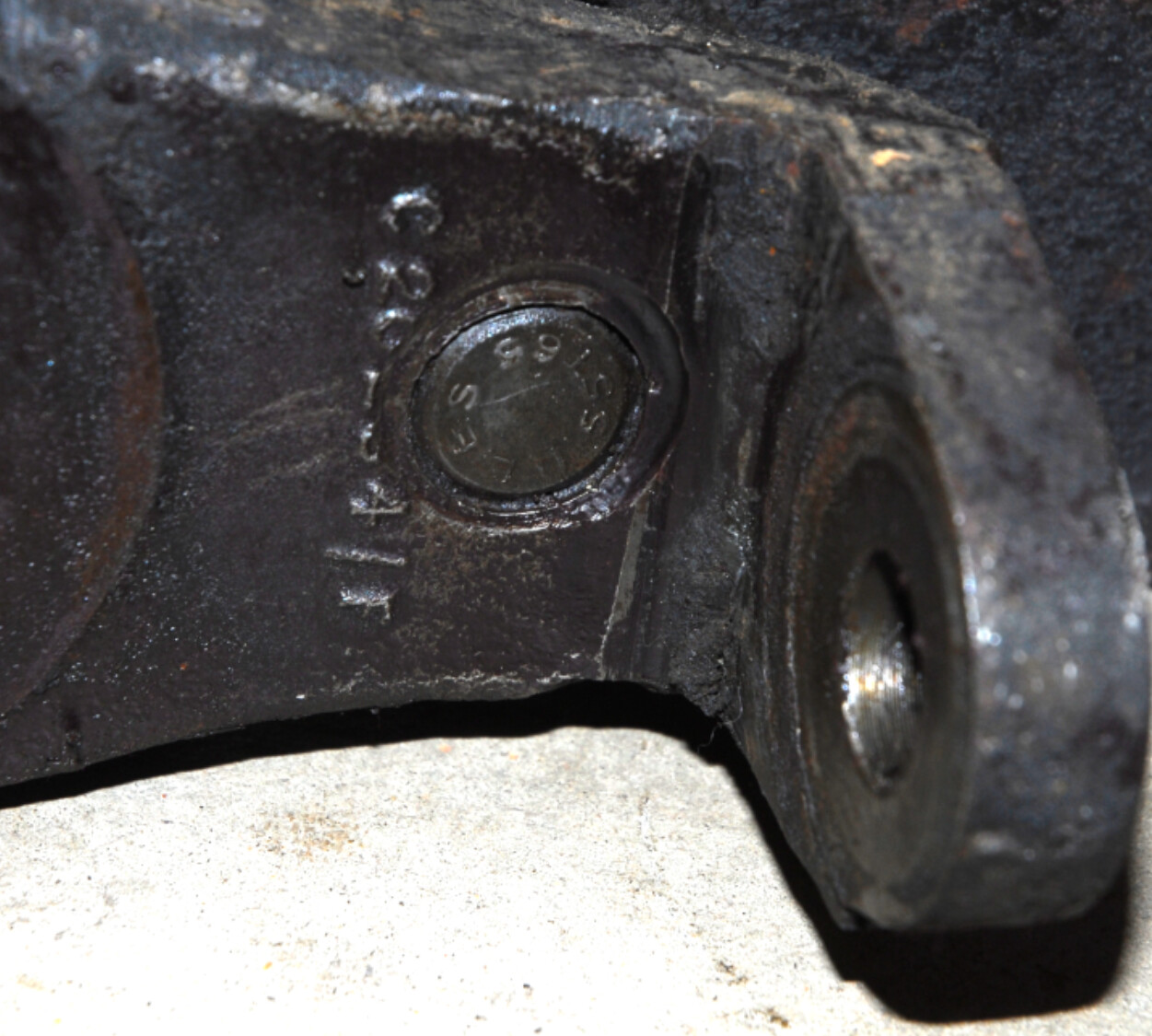
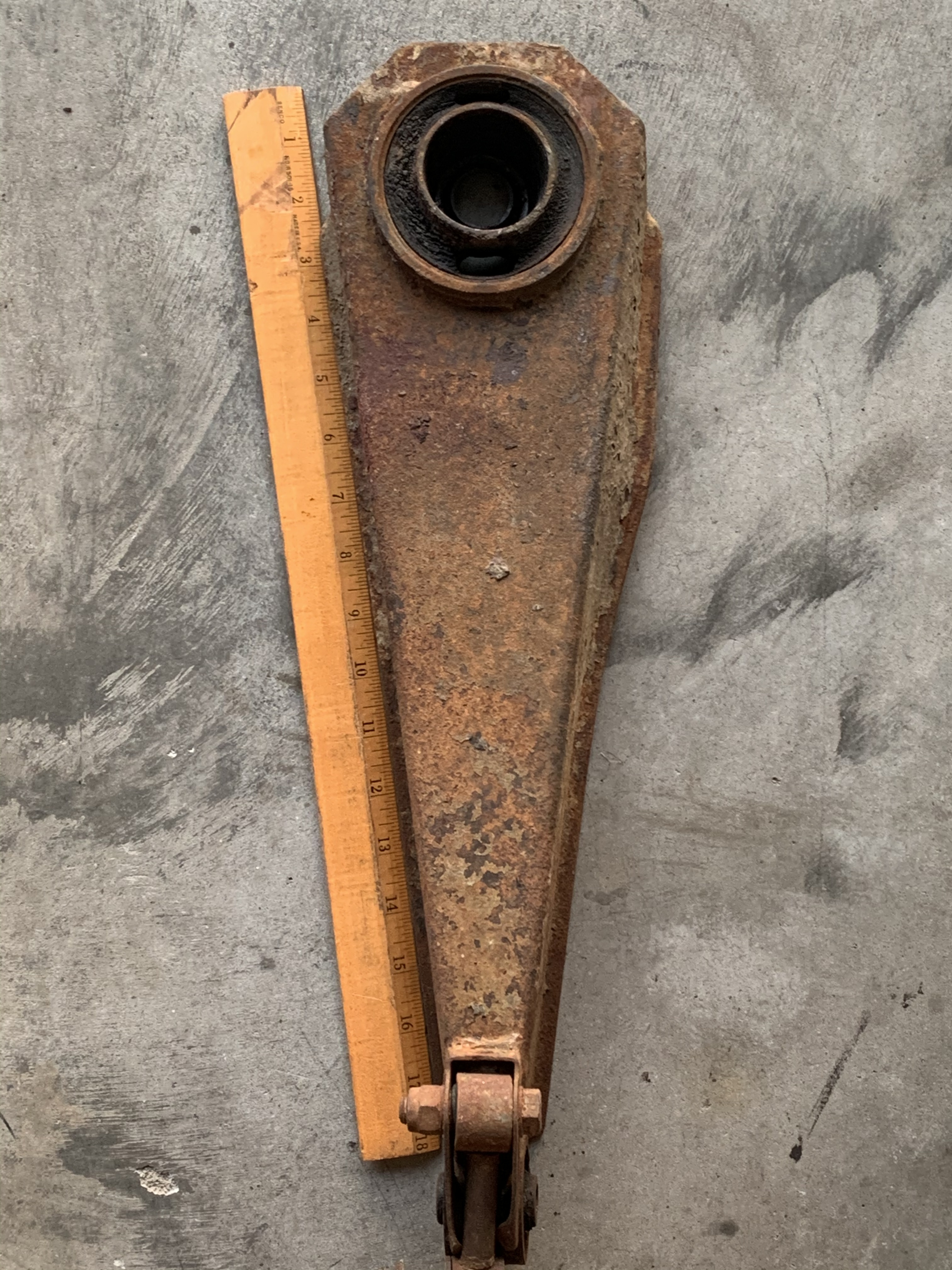
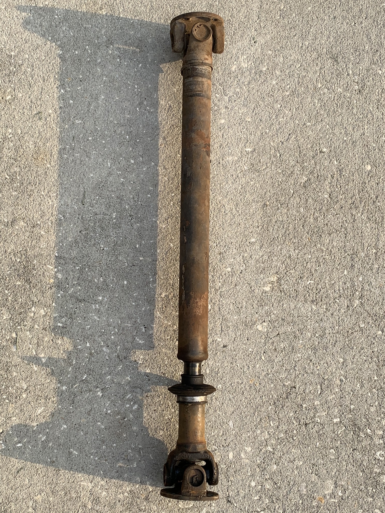
With the IRS out of the car, the shocks and springs removed and separated, and the brake cylinders removed and sent out for rebuild and sleeving, I determined the radius arm bushes need replacing and the arms themselves cleaned up and painted (or maybe replaced all together). This proved troublesome as I have the earlier style setup, where the head of the bolt securing the radius arm is countersunk in the wishbone. I removed the hub carrier without too much trouble, thanks to @davidxk’s pictures and notes for using a 5/8" rod as a dummy shaft.

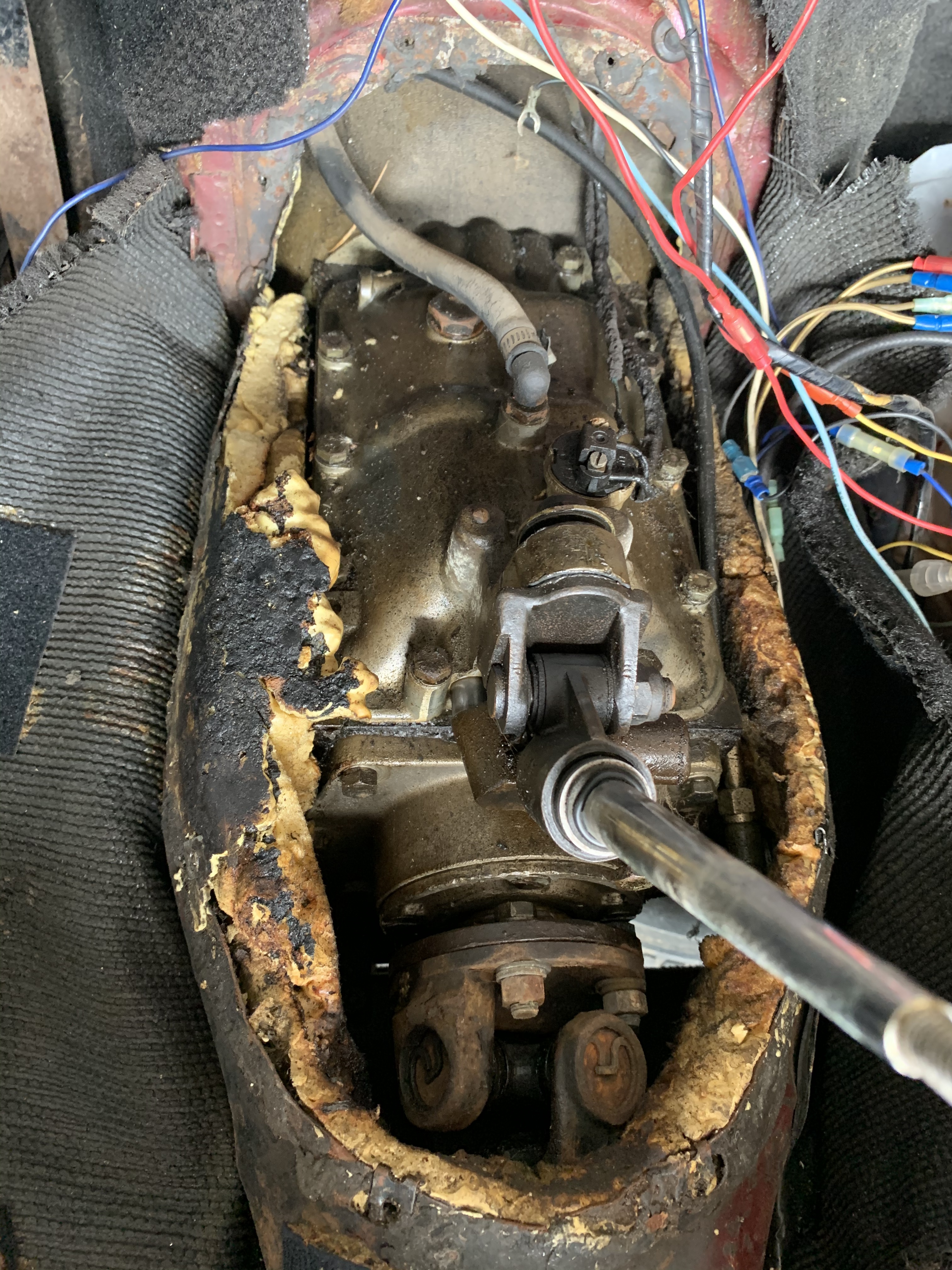
To remove the radius arm bolt, I tried using some metal shims against the shock mount and loosening the nut against them to press the bolt out, but that started goobering up the threads as I put more and more pressure on it.

Next I tried a punch and hammer, and that didn’t do much either. I tried my “new best friend”, the air hammer, but it was hard to get a good straight shot and I just ended up getting frustrated. I thought about cutting the bolt itself, as I’ve read others have done, but I didn’t like that idea because it would give me less bolt to work with if it were really stuck in there.

So, I ended up fashioning a press with some 1/2" threaded rod and a couple of pieces of 2"-wide 1/8" -thick steel flat plate. That proved encouraging as I was able to get some good pressure on the bolt, but the 1/8" plate wasn’t strong enough and ended up bending pretty good.

Ultimately, I ended up using some 1.5"-wide 1/8" thick angle iron to replace the flat plate, and that ended up working, along with PB Blaster, a blow torch, and a BFH. That bolt was in there TIGHT and I had to use the press to push it out most of the way.

Some pictures:

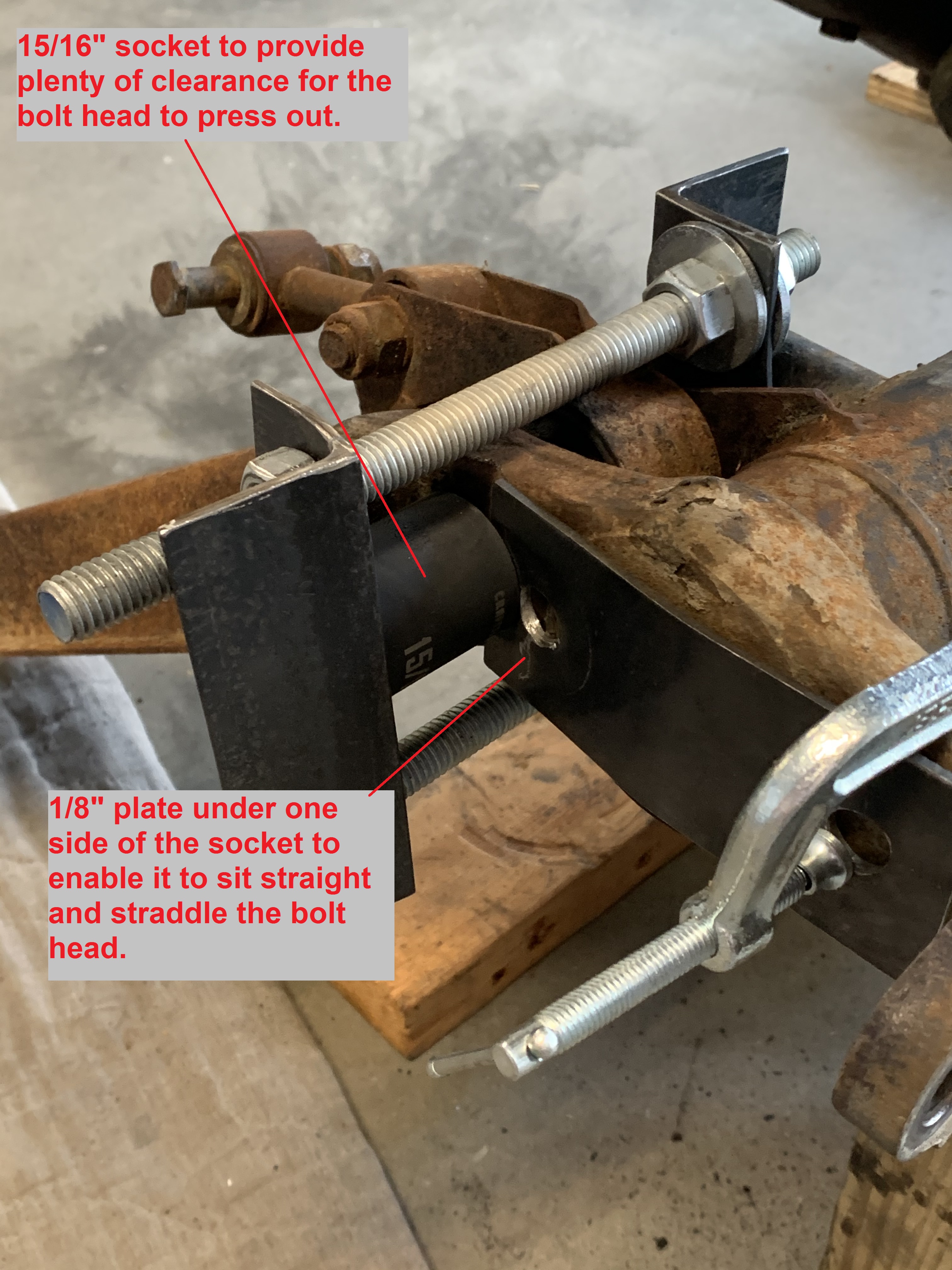
In the end, the angle iron was bent up pretty good, but it WORKED!! I hope the other side will be easier when I get to it !!
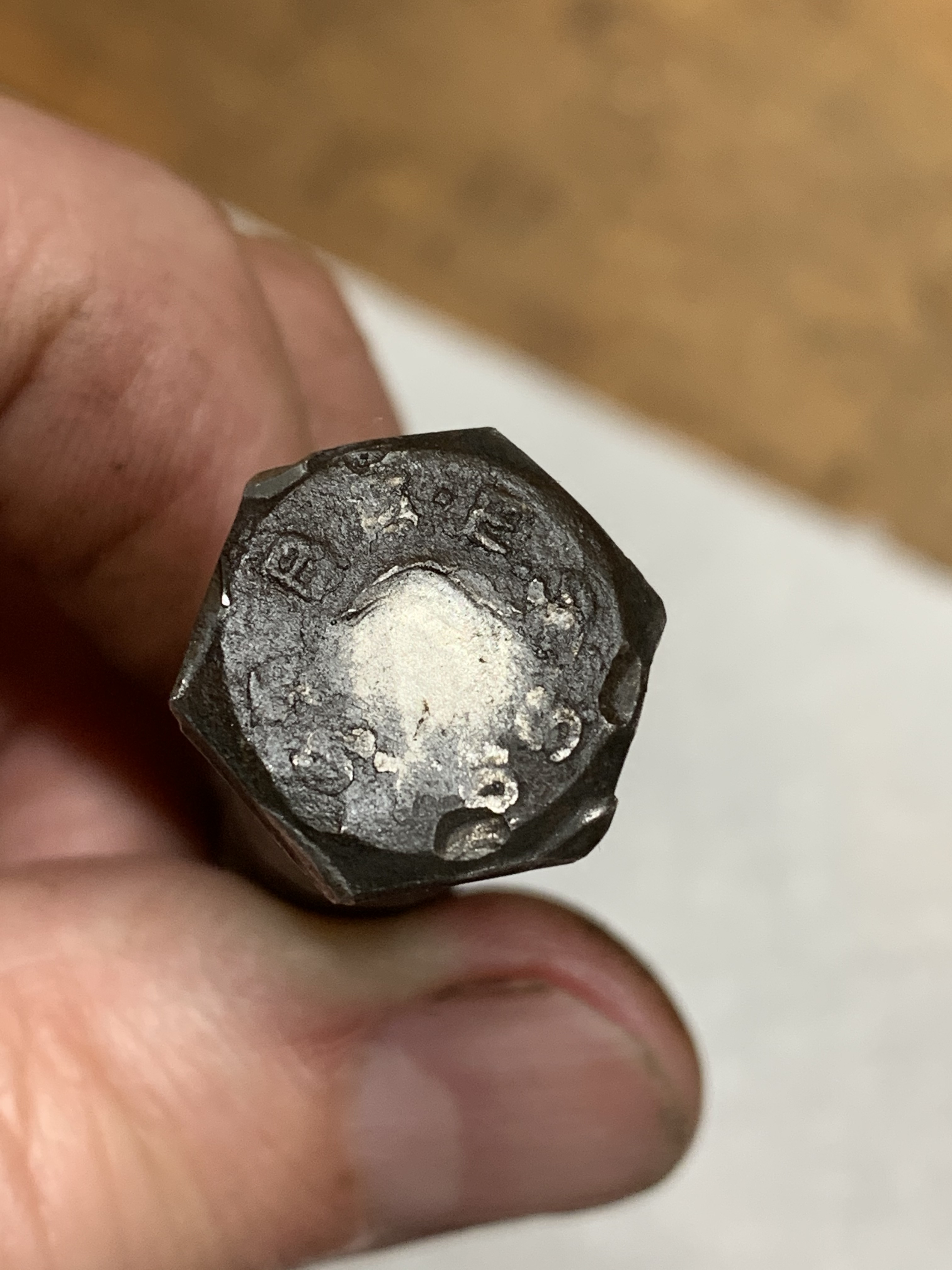
The bolt removed!

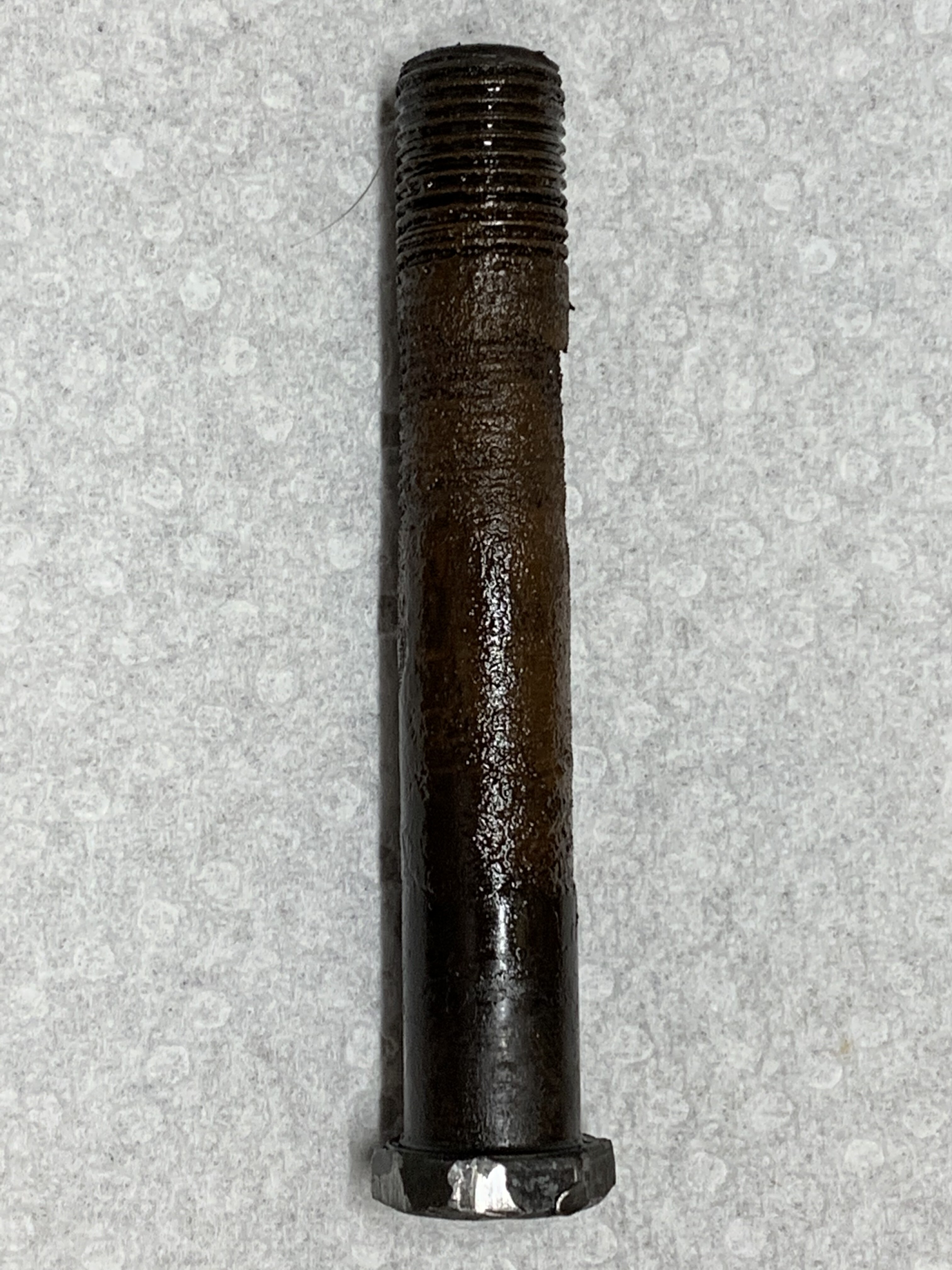
It looks to be an original BEES…

2 Likes

Nice job, if you have access to a welder you could weld a couple of 90 deg fillets in the angle iron, once you have straightened them out.

That’s a great idea that I hadn’t thought about. I will definitely keep that in mind!!

RobY

On mine it looked like the bolt head was swaged after installation. Note the damage to the casting number. This may explain why they are a real bastage to get out.

Are my radius arms bent/incorrect? From looking at pictures online it looks like the edges of the arms should be symmetrical, but as you can see, mine are not.

These first two pictures are of the LHS radius arm. You can see how one edge is straight and aligns with the ruler, where the other edge bows out:

Here’s a picture of the RHS arm. You can see it’s the same, but on the opposite edge. When installed on the car, the edges that are curved would be towards the centerline of the car.

Thanks all!
RobY

Rob,

I believe that the sides should both be straight. One of mine was similarly bent when I removed it, so I bent it back. I suspect that they may have been bent as a result of careless jacking/lifting of the car.

-David

It’s time to get out the BFH and bash those arms into shape. Mine were similarly bent from being jacked on.

Thanks David and Bill. I’ll break out the BFH again tomorrow and see if I can improve things. I’d rather try and purchase new bushes and reuse these, rather than replace both arms altogether, even though that’d be easier!

Yep: prior dipsh!t jacking points.

A bit o’polishing with a brass hammer’ll make’er right!

After the battle with the first radius arm bolt removal I wasn’t looking forward to removing the other side. However, using my bent-up press, it came out without a fight. I’ve mainly been spending my time cleaning rust and grease off the u-joint covers, driveshafts, u-joints, and hub carriers. The u-joints on the LHS were dirty but they feel good and the seals looked good after cleaned up. More importantly, they all purged the old grease out of each of the caps when I pushed fresh grease in through the zerk. I still have to clean and inspect the RHS.

A “before” picture of the RHS:

Next I’ll flip the IRS over to remove the inner fulcrum shafts and the wishbones, except I haven’t drained the diff fluid yet. I should have done that much earlier! Seeing as I’m working on this alone, and I don’t have any fancy hoists or anything, I had to get creative with what I’ve got on hand to get the IRS supported and the transmission jack out of the way -

Anyone else see a resemblance to a Star Wars X-wing fighter in this picture?

My wife says it looks more like a Space Invader. As usual, I think she’s probalby right:
image

RobY

3 Likes

And you’re right that she’s right :v:

The RHS side hub cleaned up nicely and the u-joints and seals felt and looked good. All of the u-joint caps purged grease when new grease was pumped in.

I was able to remove the RHS inner fulcrum shaft fairly easily, using the left over 5/8" rod that I had from making the dummy shafts for the outer fulcrum shafts. The LHS as a bit more work though - the 5/8" rod kept getting hung up inside, and the OEM shaft was really tight. I felt like the rod and shaft might be getting hung up on the fulcrum bearing tubes. I downsized to a 1/2" rod and with that I was able to hammer out the shaft. Post-inspection determined I was correct - the gummed up grease on the shaft and the bearing tubes was causing a really tight fit.

I haven’t cleaned and inspected the fulcrum shafts yet but I think they’re undamaged and able to be reused. Some of the outer fulcrum thrust washers are grooved pretty well, and while the inner thrust washers and seal retaining rings looked good, it’s looking to be more economical to buy the inner fulcrum rebuild kits and just replace all washers, seals, retainers, bearings and bearing tubes.

After cleaning up the bearing tubes - you can see how damaged they are. Funny how easily I was mislead by the relatively smooth motion of the wishbones, when I swung them by hand, before disassembling them.

1 Like

Rob,

Some of my bearing tubes were similarly damaged. I understand that this is referred to as “false brinelling” and is attributable to the small range of motion that the needle bearings move through repetitively. It is exacerbated by poor lubrication, corrosion, and inadequate hardness of the tube surface. I recall a thread in the (distant) past where someone did a hardness measurement of the surface of the reproduction tubes and found it to be wanting. At one time one could purchase bronze bushings to replace the needle bearing configuration, though feedback on them was mixed as I recall. Being none the wiser at the time, I just replaced mine with parts from one of the usuals. I’ve had no problems in that area that I could attribute to them, though I suspect that they now have a somewhat similar appearance.

Those are probably the ones that were offered by GTJ many years ago. Classic Jaguar was more recently offering them but I am not sure if they still do. I considered them when I was rebuilding one of my rear suspensions as they were less expensive than the stock parts at the time. Decided against them because as far as I could see the lower control arm itself or possibly the fulcrum shaft (memory is foggy) becomes one of the bearing surfaces.

I just checked the CJ website and the bushings are listed. It appears that the fulcrum shafts are used as one of the wear surfaces. Maybe not a problem as they are harder than the bronze bushings. I would be interested in anyone’s experience with them.

Thanks David! I’ve been referencing your photo album quite often and recognized the false brinelling from your pictures. I’ll be keep these old bearing tubes to use as spacers for when I do the outer fulcrum rebuild, as you mentioned in your album too. Very helpful stuff!

I searched a bit and found a 2016 post that had an email from 2009 that recommended a hardness of RC64 for the bearing tubes. Is this what you’re remembering? I’ll be calling vendors tomorrow to see if any of the current offerings are hardened. Here’s the 2016 post -

While I see some shortcomings with the needle bearings, I’m not really sold on the bronze bushings. The archives discuss the loose fit of the Classic Jaguar version. Coolcat/@Michael_Frank used to sell some that were press-in but I don’t think he does any longer. I have a call into CJ and they’re supposed to call me back.

Were the original fulcrum seals felt? The ones I removed were rubber and I’m wondering if they were replaced at some point along the way.

Yes, I think so.

I could be wrong, but I think these were always rubber. The original outer fulcrum seals were felt, though a rubber lip seal is not available as an alternative.

1 Like

I have not been on the forum in years since I sold my car…however, I just got and email tickle from the old thread…

I was cleaning my garage here in San Francisco a while back and I ran across some extra tubes that I had hardened in that batch all those years ago. Now, where did I stick them when cleaning ?

In the event I find them, someone can have them…

I miss Dick and Jerry more then I miss the car…

Best to all, James Douglas in San Francisco (JDD@8bells.com)

Thanks for the response, James! If you’re able to find them, and they’re the shorter (later) style, send me a PM and we can work out a deal - I’m in the market for them! :slight_smile:

Thanks,
RobY

After removing the IRS I examined the rear prop shaft u-joint and decided to replace it - it didn’t have the full range of motion I expected across two of the journals. After some reading in the archives I figured it’d be best to remove the prop shaft and check the front u-joint. I’m glad I did - it has some slight play, so I’ll replace both of them. Oddly, my front u-joint has a zerk, and my rear one did not. I picked up two new ones from a FLAPS earlier today, both have zerk fittings.

A few discoveries and questions (pictures below):

  1. The front u-joint bolts were secured with a flat washer, split washer, and regular nut. These should have a flat washer and nylocs, correct?

  2. Also, I found the prop shaft bolts pass through from the front of the gearbox flange, making it impossible to remove the bolts if I needed to. Luckily, the threads are in good shape. I’ve seen archive pictures of them this way, and the other way. Is one way right and the other wrong?

  1. I think my prop shaft is ~90° out of phase. Can anyone confirm?
    I think I found an arrow marking on the main section of the prop shaft (see picture), but I can’t tell if the marking on the yoke is a marking, or just a gouge. Either way, I don’t believe the phasing is correct.

Close-up of arrow on the main prop shaft:

Close-up of the marking/mark on the yoke (after rotating the assembly):

The rubber gaiter seems in ok shape, but if I have to correct the shaft phasing, can I do that without destroying it? The metal band doesn’t have any visible breaks in it - it looks like one solid band…