While I wait for parts on the differential pinion seal I’m moving out on the IRS assembly.
First question arose quickly.
The inner Fulcrum Shaft mounts. I’ve put these in place but not yet wired them. I’m reading the manual with due diligence. I had no shims between the inner fulcrum mounts and the differential. The manual says to apply the shims as required, but no direction as to what the objective is. There is a p/n for, I think, 0.005" shims and 0.007" shims. And a missive to align the fulcrum shaft. Is there a method? Or a procedure? @davidxk has a wonderful set of pics I’ve been using and his caption says, “shims used to align with holes in IRS cradle.” Does that mean the bottom tie plate?
Thank you David for the library of IRS photos you’ve made available.
I can see it coming that there are several areas requiring shims. My project has no shims thanks to the “expert” mechanic who worked on it. I will, of course, read the manual in detail, but if there is guidance as to how to adjust each area using shims? E.g., the shims for the body-to-IRS mount shims, the camber shims - OKAY, there is a procedure for that. I am finding the fulcrum shafts a bit finicky in inserting them.
The shims in this instance are to position the lower mounts so they they are tight on the diff and are aligned so the shaft can go through them and the holes in the cage. Without any shims, I doubt you will be able to insert the lower shafts. The easiest way is to loosen the bolts that hold the mounts to the diff ( the ones wire tied in the picture). Insert the shafts and apply shims to take up the spacing between the mounts and the diff. Take the shafts back out and tighten the bolts and wire tie them. This is assuming the top 4 bolts are already in place holding the diff in the cage.
No. The purpose of these shims (small square with a “U” shaped cutout as I recall) is to locate the fulcrum wishbone mounting brackets relative to the differential case so that the fulcrum shaft will pass through the holes in the bracket and the holes in the cage/cross member. Without the appropriate thickness of shims it will be difficult or impossible to line up the 4 holes (2 in the bracket and one at each side of the cage) so that the shaft will pass through. The procedure is described on page K.14 of the Bentley version of the Workshop Manual. Shim positions shown here:
Thank you Gents. I must have been having a bad day yesterday as I read Paragraph K11 and didn’t move along to K14 until last night. I should be more thorough in my reading. So it looks pretty straight forward: align the mounting bracket to the fulcrum rod and shim into place. Then remove the rod and fix the mounting brackets, torque and wire.
The 4 bolts fixing the top of the differential to the cage are secure and wired. These are the 4 bolts that were left off the differential during the last “rebuild” and also when both the fulcrum shafts were ruined with a hammer. I hope I can do better.
Here’s a photo of the shims you speak of. They seemed to use shim stock and cut out U shaped holes to slide it in, so it’s crude. I have one out of the diff but can’t find it. If I come across it I’ll post a photo…
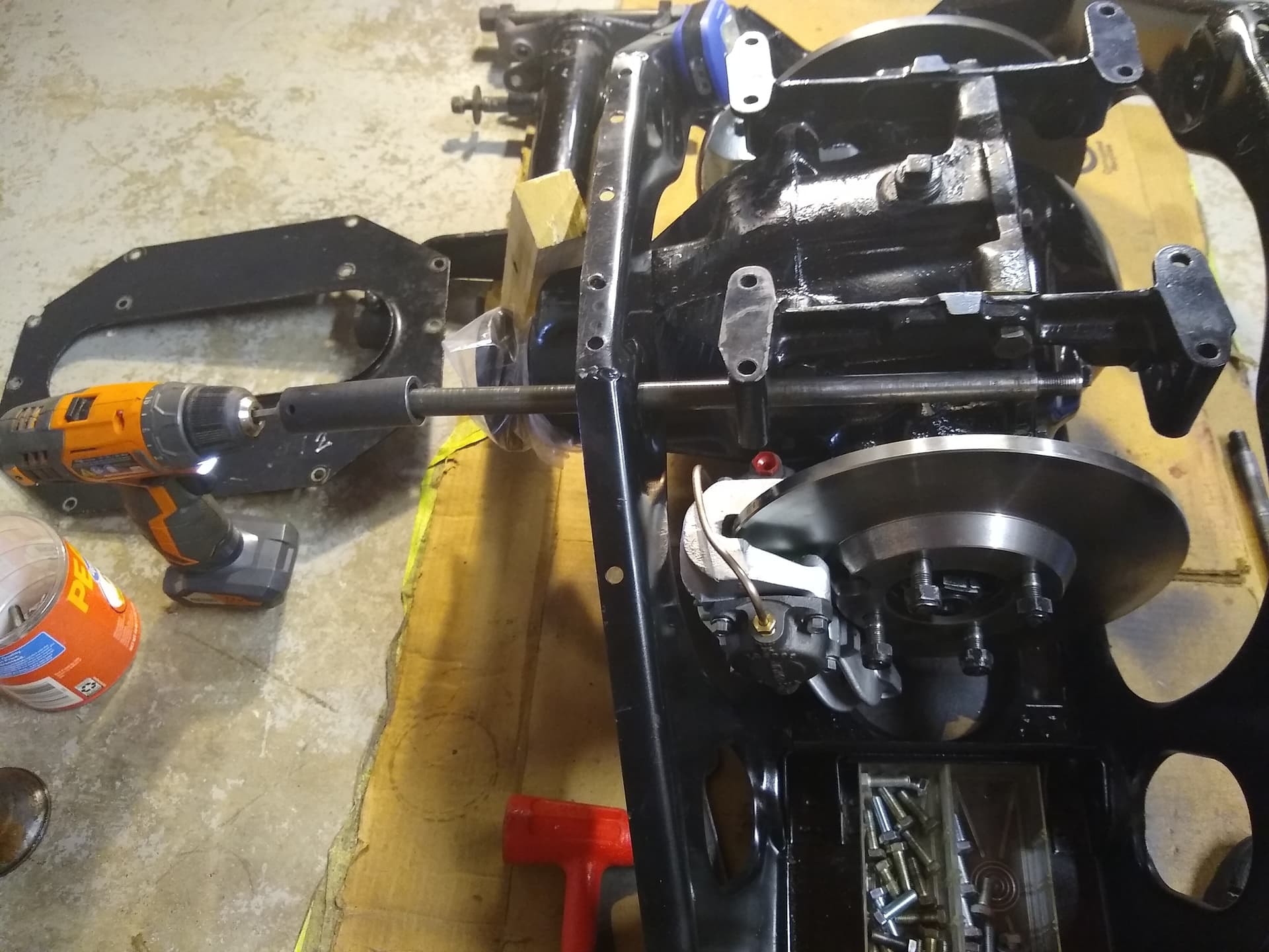
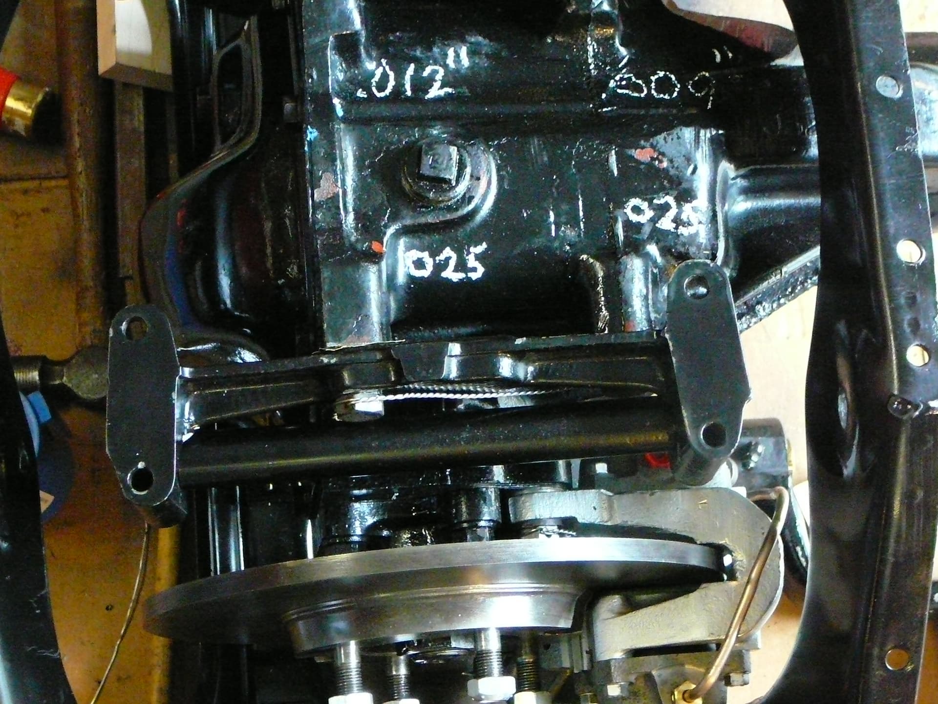
Thanks Terry. I had shim stock around so I just mounted the Fulcrum Mount very loosely, slid in the fulcrum shaft (use my drill) and found I had to also fit the bottom plate. Then I Measured the gap with a feeler gauge. I came up with 0.009" and 0.012" so that is how I cut the shims - just square “washer” shims. When I put it all together the Fulcrum Shaft went in without drama. I use my two old fulcrum shafts for alignment and also a wooden dowel. I’m thinking I might cut the threads off one end of each dummy shaft so as to let them butt together with a minimum of gap in the hopes the washers, spacers and seals will stay in place when one dummy shaft pushes the other out. I torqued these bolts to about 125 lb-ft and safety wired them.
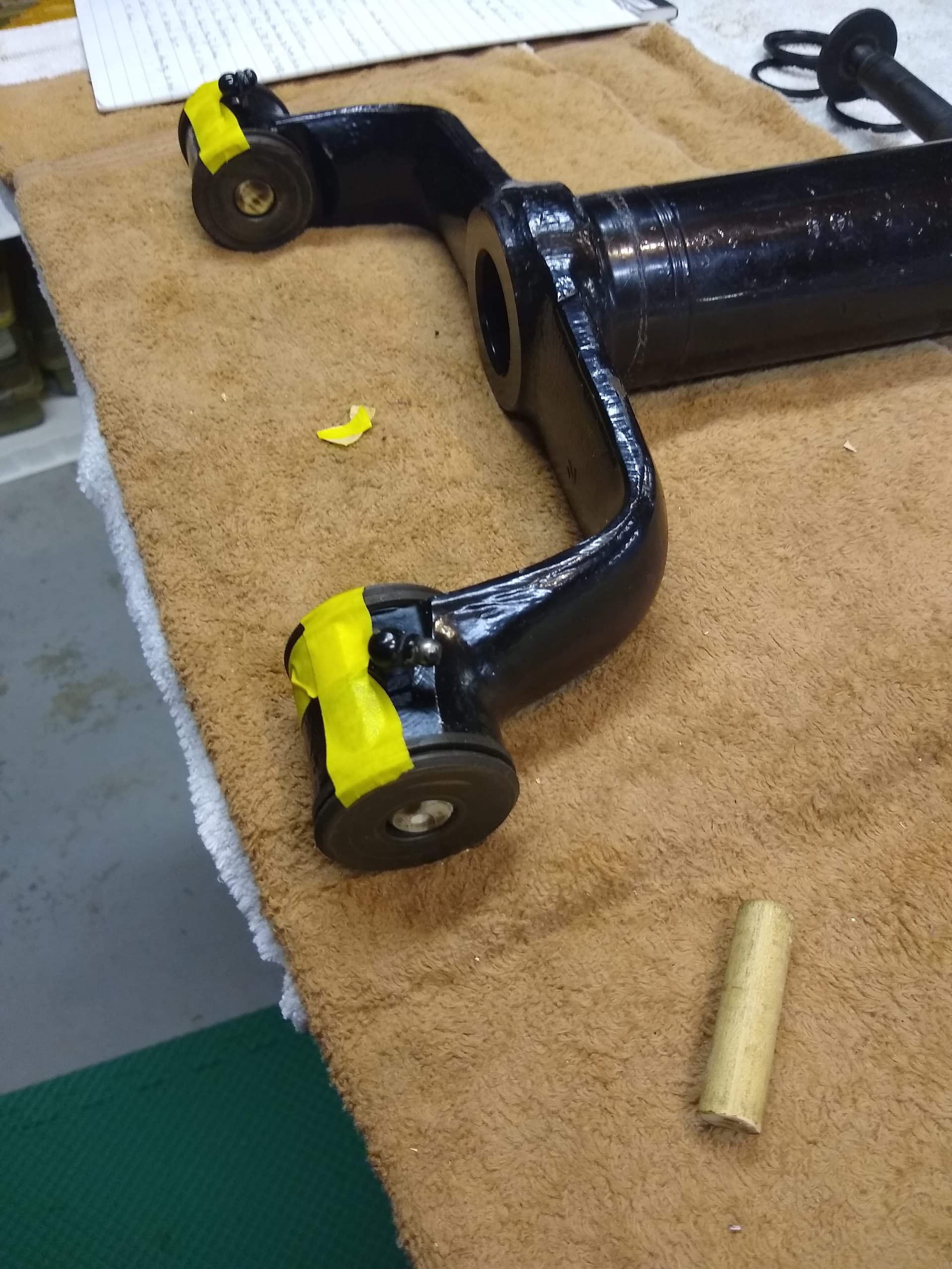
This is the right side.
One side is now finished. I made two short wood spindles to fit into the axes of the yoke to help hold the spacers and seals in place along with the tape. The spindles fit snug, not tight; I turned them on a lathe. This process worked quite well and it all went together on the first attempt. I used an undersized long wood dowel to align the holes and then used dummy shafts (old fulcrum shafts) to shove the short wood spindles inward, one on each side. With those started, I just tapped a dummy spindle all the way through and then put a short spindle back in to force the dummy back. With that, I took the real shaft and tapped it through the fulcrum pivot, using the short wood spindle as a cushion, and forced the dummy shaft out along with the short wood spindle. This left the real shaft in place without any misalignment of the spacers and seals.
It took a while for me to make the short wood spindles, about an hour, but with that the whole process went smoothly. I would not say the fulcrum shafts tapped in lightly, but they did not have to be forced in either. Just a steady tapping with a dead-blow hammer.
I think I’ll mention for those who haven’t inserted Fulcrum Shafts before, that it is very helpful to have two dummy shafts as the manual states. This allows for a bit of misalignment on each side of the yoke and makes it easier to get the shafts started. Then the one side can be used to push the other dummy out of the yoke. I also found it helpful to have a tapered shaft to get the shaft started into the yoke. I actually used a pool cue for this and it work fabulously…just the right amount of taper and yet perfectly round.
Terry, that’s Brilliant! Best to have two though I think; one at each side for that initial insertion. What did you use to hold the spacers/seals in place while you slid the yoke arms into position?
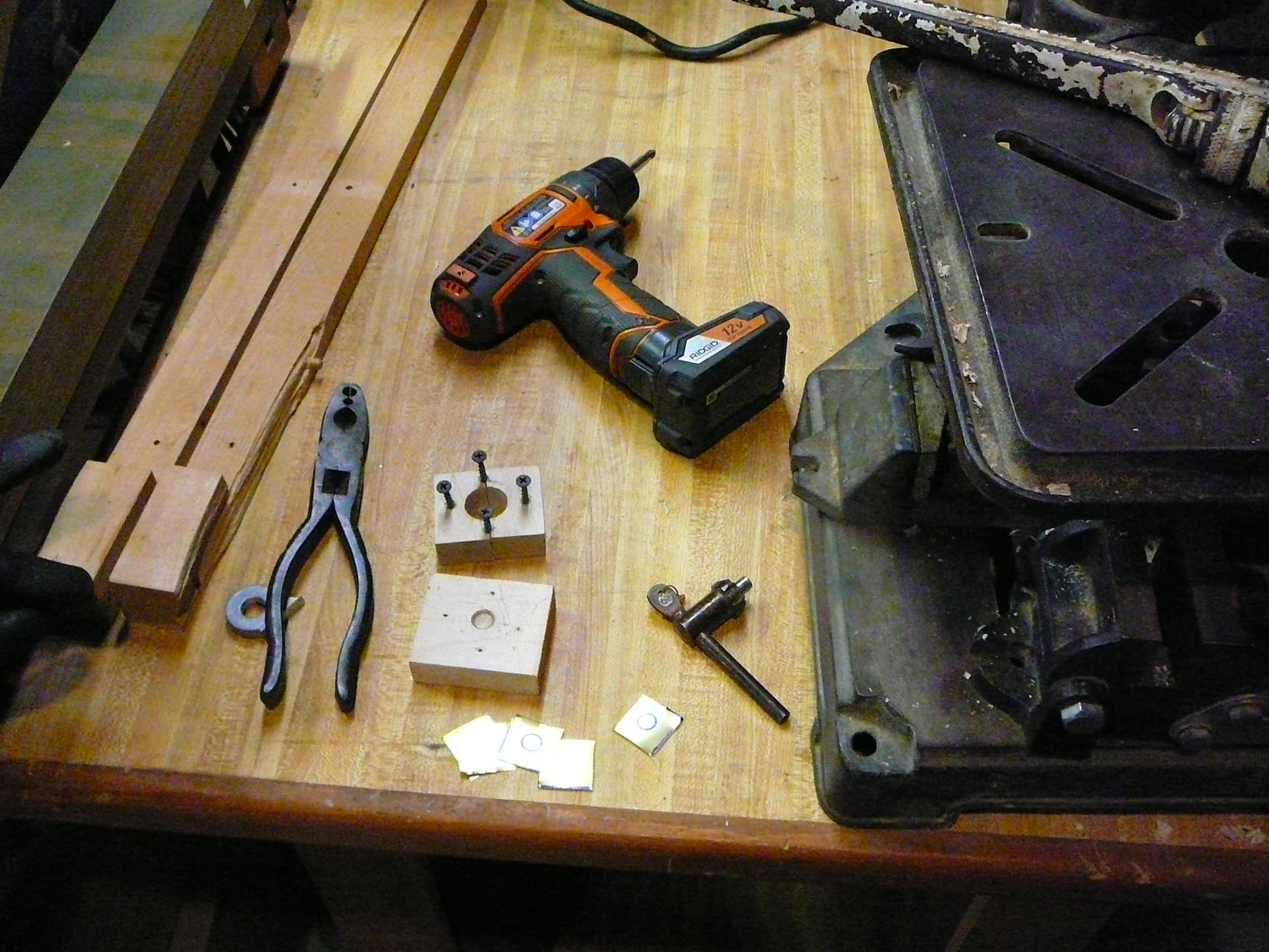
Making the shims. I decided to make the shims like washers vs. like a U so they cannot fall out. As the shim stock is quite thin I made a tiny press to hold all of them at one time to drill a center hole.
On this Left side I found 0.025" fit both the front and rear Fulcrum Mount bolts. I just have to torque and safety wire the bolts and insert the Fulcrum Shaft and this task will be done.
On to the camber alignment. Anyone with advice on that? Tips and Tricks?
I use a long 1/2" punch to set it up, and have someone hold the arm in an approximate position. Typically I need to insert the large outer washers (tapered circumference) individually as the shaft passes through as they are held in only by the shaft of the punch as it passes through. Then I insert the pointed end of the real shaft with the tool installed and that aligns everything up.
Ahhh, thanks Terry. That is different than what I did. I found out after the fact that Jaguar sells Short Dowels for the purpose of holding the assembly into the yokes just like I did. It is easy to make them out of wood. But hopefully I won’t be doing this again! Wish my metal lathe was working.
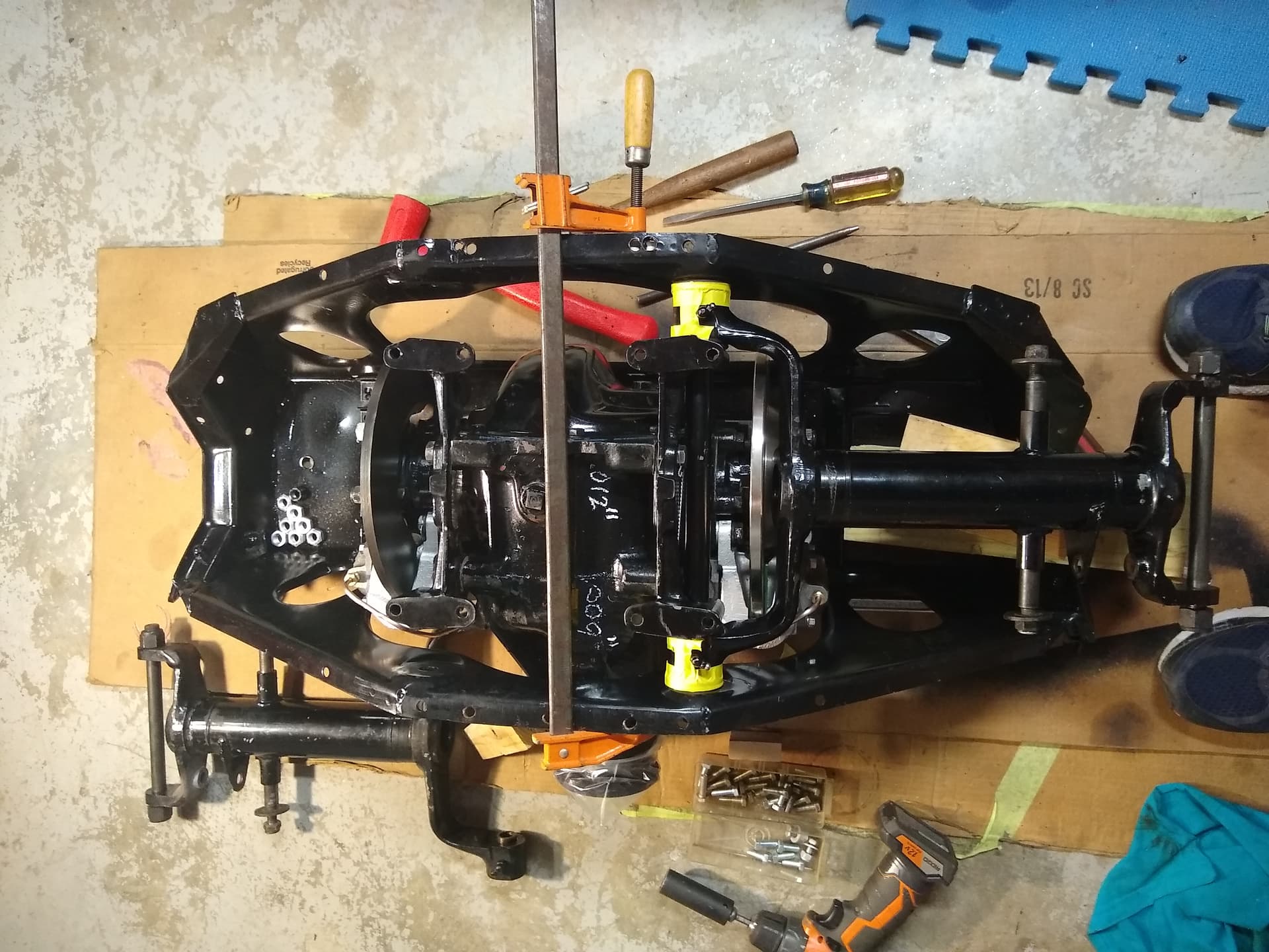
Here’s the Left Hand Side now done but no Fulcrum Shaft inserted yet. I had to repaint the wishbone, so I’ll insert it in the next day or so.
The camber adjustment is straight forward. Just be aware that when the car comes off the lift/hoist the rear wheels will exhibit camber lock caused by the tires inability to slide laterally across the floor. It would be best to drive the car around the block before measuring it, and thereafter after every adjustment that will be measured. Installing just two non locking nuts on each half shaft stud makes it a bit easier to remove and shim them. You can remove the knock offs and measure camber on the circular face of the hub. It appears to be cut 90 degrees to the spline.
thank you Terry. I certainly appreciate your time and expertise.
On the camber, I thought it was set initially with the IRS not in the car but on a level surface and using turnbuckles or the like to adjust a plumb bob to a spec.? Maybe that is the preliminary adjustment?
What about those shims that go at the IRS-to-Body brackets? I have none there, but a friend, @amcrae , did send me some he had left over. Is the objective there to just center the brackets on the frame?
I set the camber off the car in the manner you describe (photos on my website tinyurl.com/zgjkej3) and then checked it after installation - it hadn’t changed.
I replaced mine in the exact same location I removed them but I often wondered if they were meant to center the IRS to the body( same gap between the tire/wheel and fender on both sides). Or to adjust rear end tracking?