The harder the fight the greater the satisfaction when you finally win.
I recently had a tussle with a seized trailer axle bearing. I finally resorted to a cutting torch to remove the outer bearing. Only slightly nicked the axle. The bearing had spun, got hot and then seized on the axle, then cooled and shrunk…
Yeah…that sounds familiar. Funny how we remember those “good” times. 
hardwood has a big advantage over steel, in that if the bearings, shims and seal become mis-aligned, if you use a steel rod, you will destroy the parts…a tiny chamfer helps
dont like to be a “scaremonger”, but I hate knicking things like that, because that sets it up for a stress crack to deveop
The boat weighs 145 pounds. It’s a 1 inch axle with a slight nick the size of a grain of rice in the top of it. I am not the least bit worried.
And you are perfectly safe with that: I’m sure the stress riser it put in there is nil.
Yup I’ll just take this apart and change a shock it’s only two bolts are you listening Tom with the barn find
Jim
II put that sh&$ on everything and whenever I take something apart i just smile
I hear you Tony. I have the oak wood (and poplar) dowels in my shop and so I’ll give it a consideration when I re-assemble. I actually like the concept of the 15mm copper pipe, but haven’t found that in this country.
Seeing as I’m using this to document my project, I have noted the bolt I cut was a BEES bolt. The one that came out easily doesn’t have any marking on its head. More evidence that it had been replaced.
And yes to anti-seize. I’m going to have to get more that I can “paint” on. Mine is a tube to rub on the threads; not so good on smooth surfaces.
That’s what I used and it works great. The ones I used came from the big box home improvement store, I’ve no idea what kind of wood they are (pine, poplar, who knows, but they worked. I did need to slightly reduce the diameter with sandpaper but that took just a couple of minutes.
Update 2/10/2022
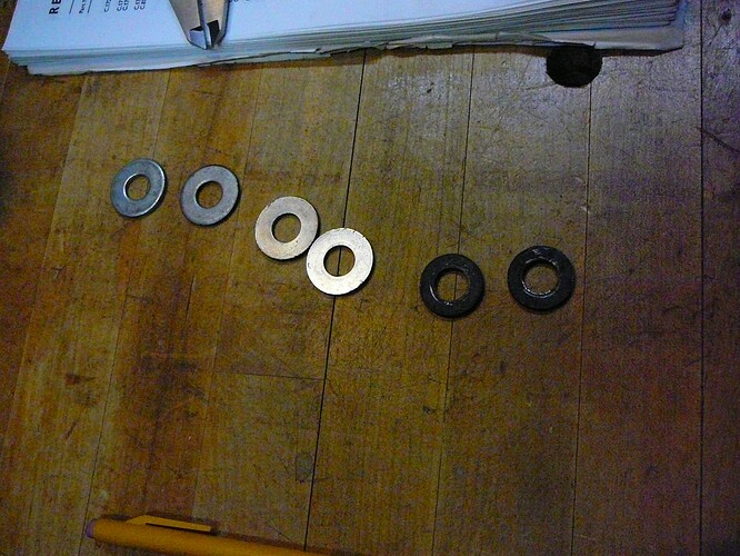
I’ve been dismantling and cleaning and checking stuff. Found the rear brake calipers were very crooked in relation to the brake disc. Not good. The miscreant rebuilder used fat washers for his shims that make no sense.
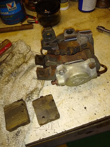
Anyway I took the brake calipers off. Found a problem with the left side caliper bracket in that one of the mounting ears was fractured. It broke off with little effort. Note the coloration of the break; this has been fractured for a long time and only the shiny (or whitish in the pic) break is what I did. Got one from Dick M. This was not a good thing as it surely would have broken in use.
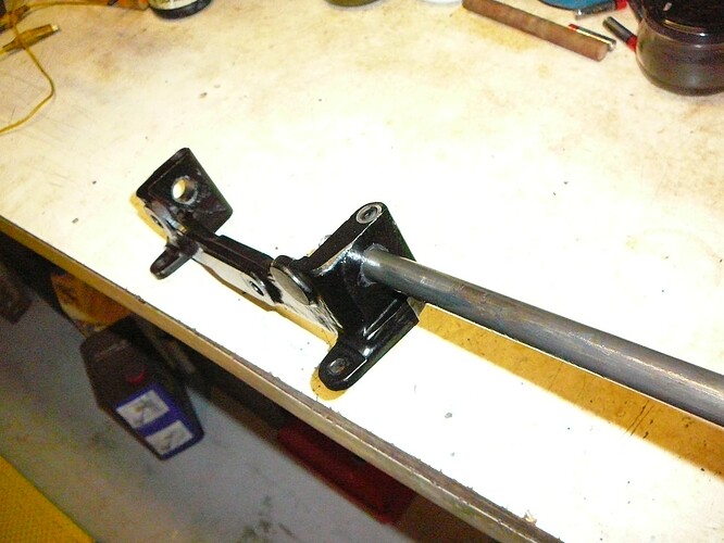
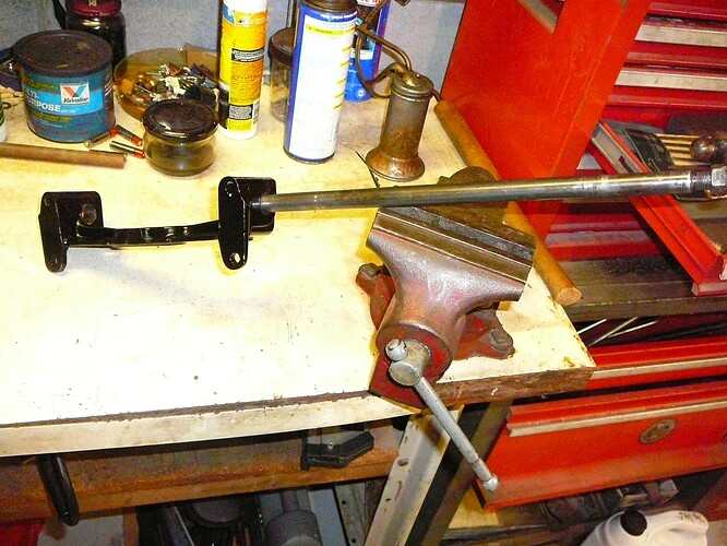
On the fulcrum shafts more problems. You might recall I had a thread about removing a nut-missing fulcrum shaft in situ. That did not work and I decided I’d attend to it when I pulled the IRS. The inner fulcrum shafts were extremely tight and needed a big hammer to remove (see way above). Well the fulcrum shaft that had nuts on both ends was also damaged. I could not re-install the fulcrum shaft into the the fulcrum bracket.
So it was not just the bushing in the cage sides that were tight, but the fulcrum bracket too was very tight. On the other hand the new on I had ordered fits snug…just right.
The nut on the fulcrum shaft that I thought was good because it had two nuts on it, was not. I had to use a nut splitter to get the nut off.
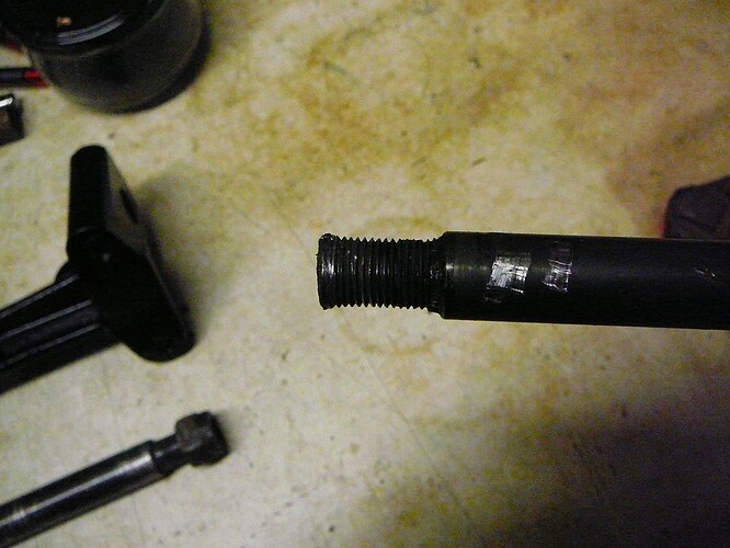
Once off one can see the end of the fulcrum shaft is swollen from abuse by a hammer. I am so glad I did not attempt to remove these from under the car. Dick M. has one of these too, so I’ll pick that up.
The new fulcrum shaft fits into the fulcrum brackets as well as the inserted bushings in the cage sides. I should be able to get it all together when the time comes.
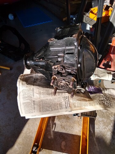
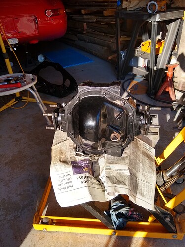
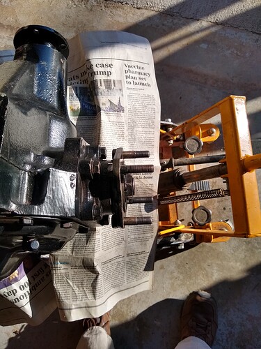
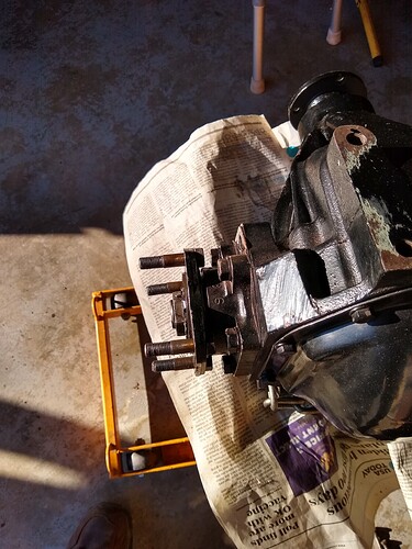
One of the advantages of the motorcycle jack is that it is sturdy and very steady in its raised position and that makes a nice work bench.
I have a little stool and I roll the differential into the sunshine coming in the garage door. Its a nice place to work.
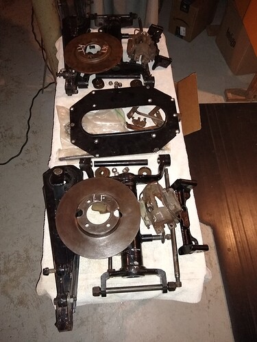
Here’s a picture of the disassembled parts. I am not going to take the differential itself apart.
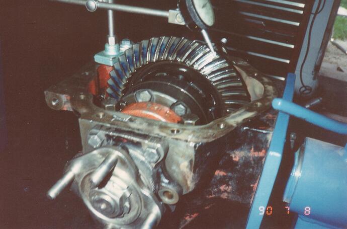
It appears to me that differential has been repainted and the cover was powder coated. I don’t feel any end-float on the shafts, but I’ll check that with a dial indicator.
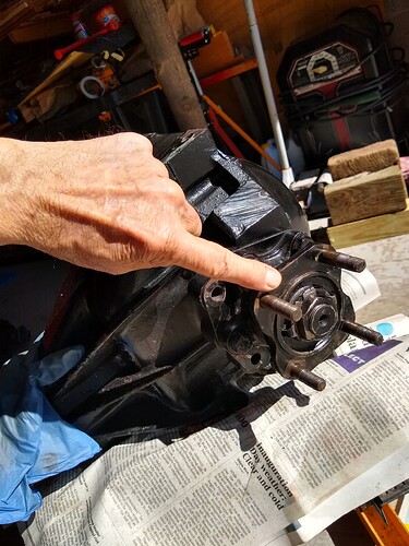
The next problem: I have 3 different lengths on the differential output flange bolts. Several are, I think, OEM, but others not although they are a hardness 5. So here I ask for some advice.
Should I replace all the bolts? I inspected them carefully thinking I may have noticed some stretching, but I think not. Some of the bolts look “crooked” but that is because the ends have been damaged a bit on their ends…making an optical illusion. I have thread repair tools and I dressed all the threads and finally ran a die over them. With the die I cannot feel any tightness or looseness over the lengths of the threads. I think they are all consistent in diameter. I think the factory bolts (4HU-055/4, p/n 8510) are 2-1/8" in length. Some of mine are 2-3/16" and one is 2-1/4". The factory ones fit very tight into the their flange holes, some of the others I can slide in and out with my fingers. So, what to do? They are $11 each, so mol a $100 bill. What do you all think?
Also, to change the bolts, I have to remove the flange. That’s not a big deal, but I wonder if I’ll have to replace the seal if I remove the bolts.
Another question. I note that there is paint on the mating surfaces on the output flanges and the one-half shafts. Should I remove this paint? I am used to mating surfaces not being painted, but perhaps it is irrelevant in this case?
And one more item. Those captured nuts that the handbrake bracket bolts too? Well, they were regular nuts and a real pain to remove. Cut a wrench head off and welded it to a nut into which can screw a bolt. That worked but what a nuisance! I can’t find these nuts at the usuals, maybe I’m not looking hard enough?
Cheers all and back to the project.
Yes, you need to replace the output shaft bolts. They are a special press fit and a regular sloppy fit bolt should not be used. I had to replace a few on my 64 due to the threads being damaged and it is not difficult. Yes, replace the seals. If it were me I would also open up that diff and clean and inspect it. Everything you are finding indicates very sloppy work by someone and I would not assume that anything is in working order.
Thanks Geoff. I was thinking I could remove the output flanges. It looks like that is pretty easy to do. But in the manual it indicates that the output flange is to fitted up and then the end float measured, adjusted as necessary and only then is the seal to be installed and then the final fitment of the output flange. I think that means that the output flange fits into the seal and hence the seal should be replaced if the output flanges are removed. So, I agree with you.
On the output bolts, I have now inspected them closely. On the left, the bolts are all original. Measuring them from the bottom of the head to the end of the threads (earlier in this thread I simply measured the overall length), they measure 1.803" to 1.805" On the right two of the bolts are original and measure the same. The other two are 1.95" and 1.97" respectively. I misspoke as I said they were Grade 5. They are not, they are Grade 8 (6 radial marks). Still, they do not fit snugly as they should. I’ll change them.
So I’ll need two bolts and one seal and one lock plate. I still haven’t measured the end float so that may change things.
And I’ll take your advice and remove the cover and inspect the insides. Better safe than sorry and we all know pulling the IRS again ain’t fun. BTW, I turned my diff. input shaft 10Xs and got 3-1/3 rotations on the output shafts. This I believe verifies I have the 3.31:1 gears as this car should have.
Thanks for helping me make a decision.
Just curious, is there enough room to push the flange bolts out without removing the flange from the housing? Are the bolts typically very tight or can they be pushed out of the flange easily?
Tom
No space and they need to be hammered or pressed out.
Scot,
I used a wooden dowel. I had it lying around and it just happened to fit perfectly. Being wood, it’s rather easy to resize if needed using a drill and some sandpaper or a file if needed.
The manual says to push the bolts back towards the differential as far as possible in order to get the disc off. this is with the brake pads out. I just took the calipers off so I didn’t try that. But the factory bolts have to be hammered to move. I used a brass drift and my hammer and then switched to my brass head dead-blow. The bolts move fairly easily, but not by hand. And they will not clear the flange before interfering with the bearing housing.
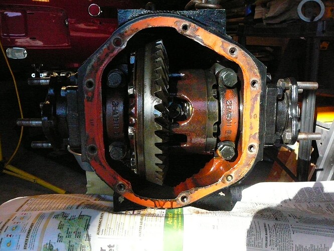
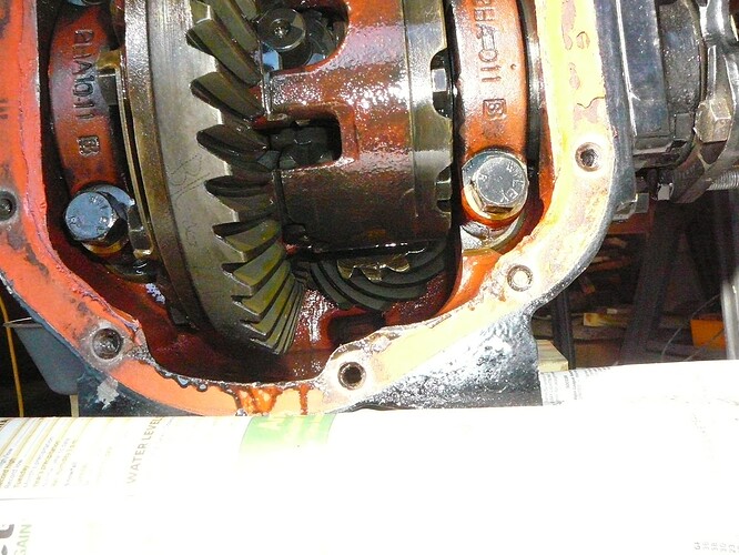
I drained it and took off the cover. Pics coming.
I drained the oil. I had remarked on the oil in the beginning of the thread as it seemed clean and was a small quantity. Well, it is clean. It’s a nice amber/reddish translucent color, smells clean and there was about an ounce maybe two.
The insides look very clean. I checked the bolts for their lock plates being in place…all is there. I have not made a gear pattern for over 50 years, but I’ll get a closer pic tomorrow of the wear on the ring (crown) gear. But it all turns smoothly and with hardly and back lash. I’ll try to measure that tomorrow.
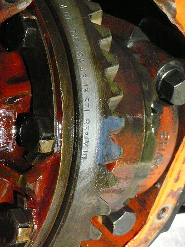
On the edge of the crown gear are two sets of figures. One is scribed by what may have been an electric engraver tool. It says (I think) B/L [infinity sign] 7D 2464. This program won’t let me type an infinity sign but I know how to (alt + 236). I do not know what this means. If anyone has an idea…
The other set of figures is stamped and it is, 4HA - 016 - 8A43 13 STI R 62Y 10 I don’t know what that all means either so if someone knows, clue me in please?
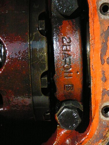
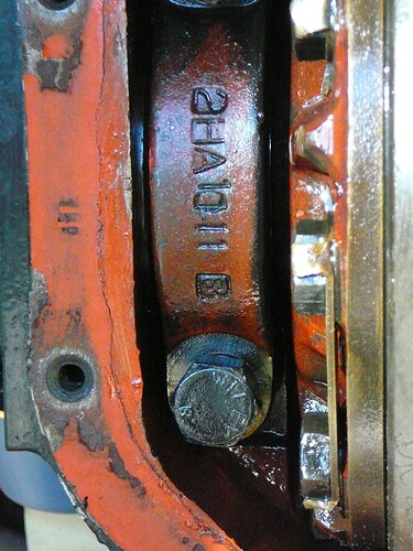
And the bearing caps have stamps on them:
And finally a close up of the pinion. I didn’t count the pinion, but the crown has 43 teeth.
So what should I do now to verify the differential is in good shape?
Scot, that’s probably a good idea so if you do, here’s the pattern I got for comparison after I’d renewed the diff side bearings on my '62. The patch could have been a bit nearer the toe but the axle was quite quiet after the rebuild.
Re the output shafts, the 4-bolt flange can be removed by itself and the seal is right underneath if that’s all you need to change. I set my end float to .0015", the mid point but folks here have been recommending zero or even a preload. Here are all the bits inside.
Thx for the pics Clive. What is the blue paste you used to mark the pattern? Last time I did it we used white lead. I’ll have to look this stuff up and read all about it again. Well, it makes for a fun project, huh? And very rewarding (at least for me) to say, “I did that.” @davidxk Langley has a great picture essay that shows him measuring end float. I have found that very useful.
The stuff I used to use.
