Scot's Rear End -- The IRS

Instead of answering individually, allow me a combined answer.
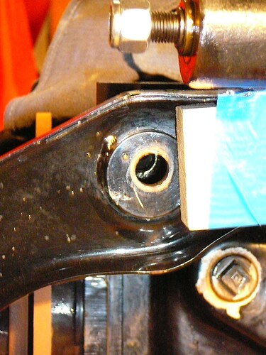
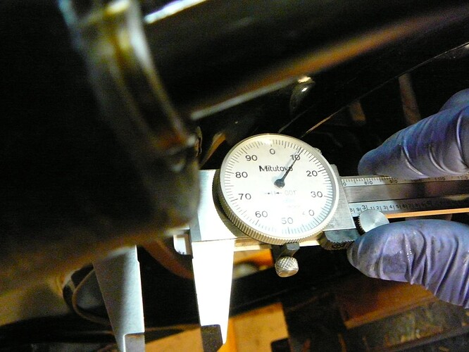
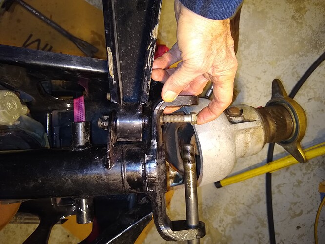
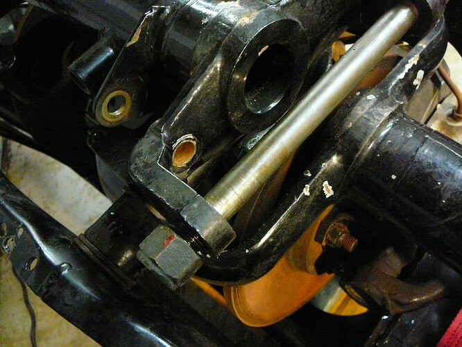
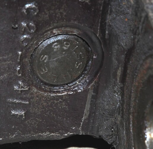
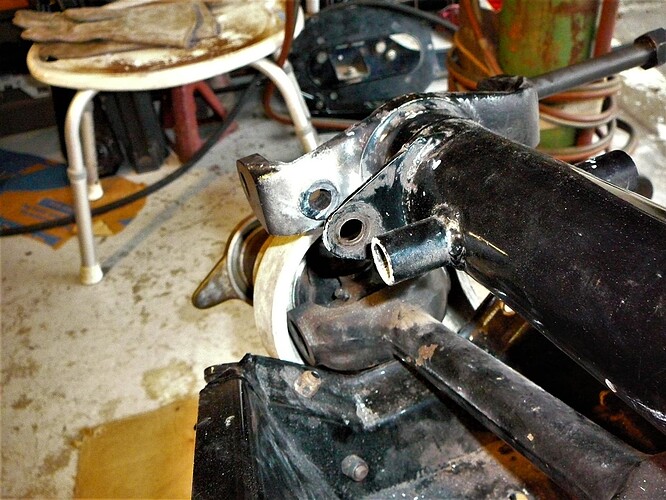
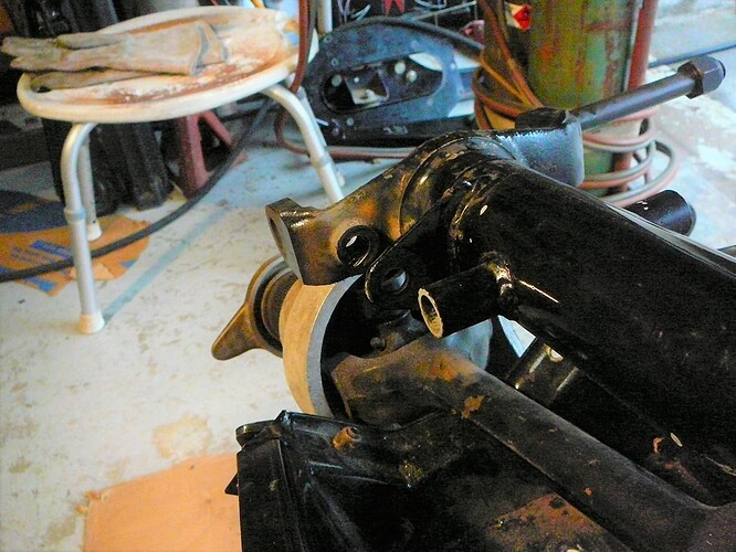
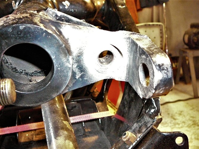
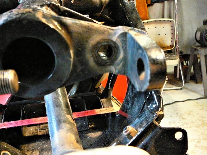
Steve, all four holes in the sides of the cross member (cage) have bushings in them Indeed this is the cause of my having to pound the fulcrum shafts out. Pics:


I could not re-insert the old shaft into these bushings and I could not insert the new fulcrum shaft, nor the 0.622 steel rod I bought. I could on the one side but not the other. These bushings are not round but are oval between 0.611" and 0.622" or so. I did not know they are not OEM. I can ream them to fit.
Dave, I know that’s what you did and I have dowels in my shop. But I was whaling on the steel drift and wood would not stand up to that, nor copper pipe. On copper pipe there is several types: L, M, and K. I forget the sizes but the Brits are lucky as their 15mm works just fine.
Danny, 23-1/4" then. I’ll remember that. I know I would not be happy chasing IRS parts down the road.
Fortunately I have only “driven” it in my driveway although I did make one trip to the bottom and back - 750 ft each way and coming up the drive was a bit scary with all sorts of noises. I knew the IRS had to come out!
More update:
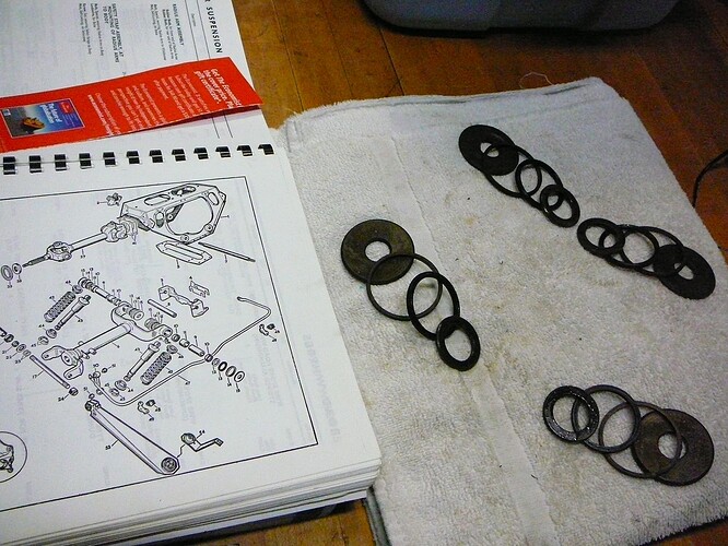
My observation on the stack-up of seals and spacers was, certainly, incorrect. I hung a rag between the two sides thinking it’d keep parts separate. Not so. It all looks like it’s there, seals being trash notwithstanding.

One of the 8 axle bolts is longer than the rest.

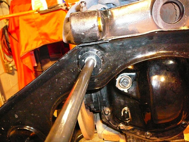
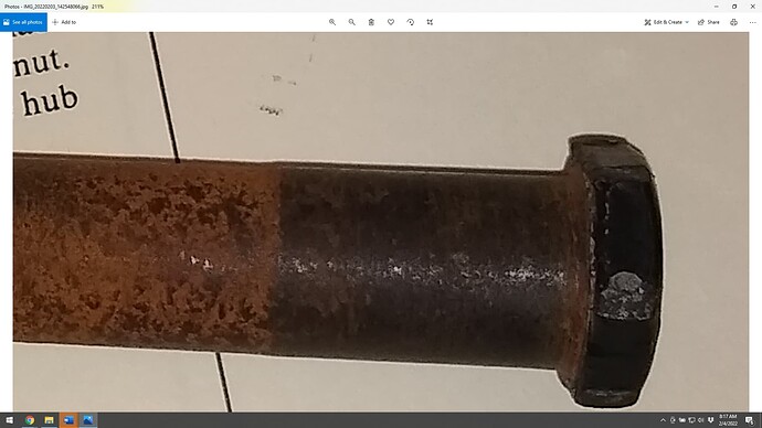
Below is a pic of the old Fulcrum shaft attempting to go in the bushing that only measures 0.611. Not happening.

The rear of the cross member has special customized bolt holes in it. If you cannot line up the bolts, simply drill new holes. You’d think I’d have thought of that!

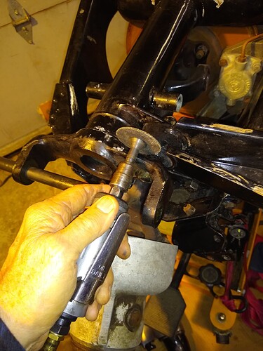
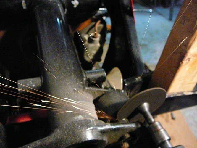
I moved on to the left side of the crossmember today. Thought I’d first remove the bolt going through the small radius arm bushing. Think again. The head is totally destroyed. On the other side, I simply used my impact drive to spin the bolt out of the small yoke/radius arm joint. On this side, the busing is age-bonded to the bolt. I can’t get a good strike on the bolt because of the shock studs. So I have two ideas: Weld a bolt to the ruined head or use a cut-off wheel on a die grinder to cut the bolt. What do you think? Maybe I could also grind the head off.


Well, that’s it for today. Back at it tomorrow.

1 Like

Is there a specification for the diameter of the fulcrum shaft holes through the cross member?

Hi Scott…something to check…there are different size irs cages…why were yours holes bushed…just becaus of damage or to alter a different cage…sorry i dont have cage details but you need to check it out…someone here will know all the details…Steve

Also note there are different diff mount brackets…you need to check yours… if the wrong ones were fitted then the fulcrum shafts wouldnt fit…so possibly someone made them fit by re drilling and bushing…Steve

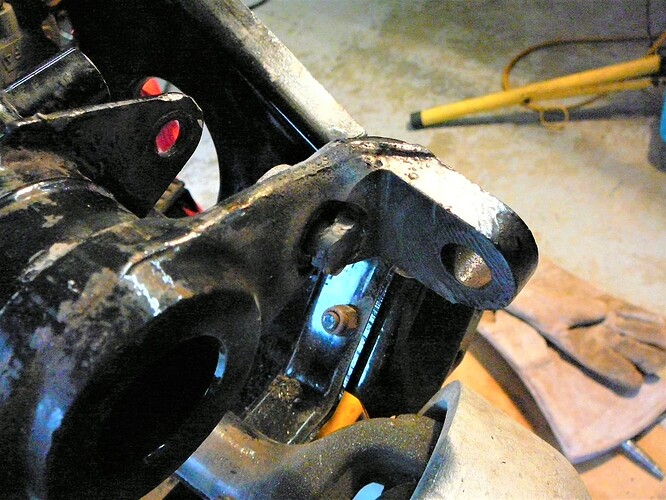
The bolts that attach the small end of the radius arm to the outer wishbone yoke are countersunk into the outer wishbone yoke and the heads are peened in place.

I had to press mine out with fabri-cobbled press tool I created -

1 Like

THAT… is going into my lexicon!

2 Likes

That’s interesting. Thank you Steve for clueing me in on this. There’s a history on this car that will be interesting if I ever sort it all out. I have the original buyers name…fellow in Texas. I have the name of the fellow who sold it to my aunt…an attorney in Salt Lake City. There was another buyer before my aunt, but he didn’t pay for the car, abandoned it and the attorney took it back and put it in this foreign car shop…not Jag specific, run by an alcoholic. The car has a picture frame from a different vehicle and the head is from yet another vehicle and the gearbox from yet another but that was probably considered an upgrade to the all-synchro box. The car was painted bronze when the attorney had it and he says it was a nice car. The title was so screwed up by the State of Utah, that I could not title it in any other state! I flew to Coventry, England to sort that all out. Some of the workmanship is first rate, other work looks like sabotage, lots of pieces missing but then lots of good stuff also. It is an interest adventure to be sure.
If anyone knows the story on the E-type cages, please let me know?

I think we can fill in the details…:scream_cat:

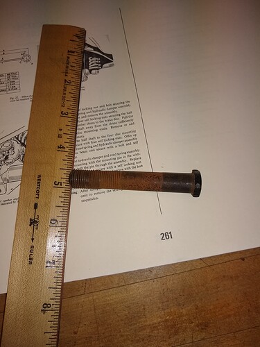
Thanks Rob, but that doesn’t fit with what I observe on the one bolt I got out. It is a special 1/2" bolt with a half-width 5/8" head; otherwise, normal looking. The seat for it is machined into the small yoke about 1/16" or less…not very much. The bolt was not peened that I noticed and I simply put a socket on it and turned it out while holding a box wrench on the nut. It came right out. I don’t see anything that it could be peened to to prevent it turning. Maybe I need to look at the manual again. Anyway, the one I’m having trouble with is just mangled by an ill fitting socket, or perhaps ill tempered mechanic. The flats are all rounded off. Pic is of the good bolt and the recessed hole is came from. I wonder if there was a change for later cars?


Wiggles, do you know anything about the different sized cages?

I do not: that said, make sure to use lots of antiseize on bolts that go through other units that are not otherwise greased.

1 Like

This is what my radius arm bolt looked like when I got to it:

Total biach to remove these- I had to use the nut on the back side and various spacers to press these out.

I think we’re saying the same thing, Scot; maybe we’re just not describing it well to each other! If you click on the link I gave in my last post you can see that my bolt looks just like yours. And when installed, it looked just like the picture Doug posted above.

Doug had described it as possibly “swaged” in place so maybe that’s what I meant, rather than “peened”.

Yes, I believe there is a change for later cars. I believe beginning with the S2 cars the bolt has a special 5-sided head (to allow it past the shock mount) and the wishbone holes are threaded. Looks like we have the special, cumbersome ones!! :slight_smile:

When rebuilding my early 4.2 IRS, I converted it to the newer design. Somewhere there is a post on this, but basically you need to shorten the front lower shock mounting tube (and fab or buy a spacer to replace the cut off part) and press in a nut (I used a ny-lock) where the former bolt head resided in the control arm. And finally your new bolt head needs one ‘point’ of the hex head cut down flush with the bolt shank. Pretty easy and obvious, especially if you look up a parts diagram for s2-s3 cars.

Hi Scott, my recollection of these (but going back 25+ years) is the shank of the bolt immediately under the head had a short length of serrations which engaged into similar serrations in the small yoke bore, to prevent rotation of this head. These were quite fine serrations and I suspect could be readily destroyed by a combination of corrosion and/or someone trying to rotate the head (or a seized nut) to free things up.
But that’s just my (possibly faulty) recollection - I haven’t needed to go back in there since….

1 Like

what the other guys said about the radius arm bolt, I have dealt with both types without much issue, you do need metal plates and nuts to drive the older style out. The newer style is much nicer to deal with

I like to use the right anti-seize or loctite on the fasteners, someone will love you in 30 years (or maybe less)

For my last IRS over haul, for the fulcrum shaft rod, I made up 3 lengths of 5/8" hardwood dowel, chamfered the ends very slightly.

Now I cant quite remember exactly why I came up with the 3 lengths idea, but the 2 shorts ones go through the bearing area, and the longer one goes in the middle.

I can tell you it worked an absolute treat, and I threw them in with my other home made Jag tools. It allows you to set things up easier than one long piece by my recollection

shame about the out-of-round inserts :nauseated_face:

I wonder how true the plane of the bore is on that component …ie is it distorted somehow

HI Scot…info here on cage sizes…probably not your issue but was worth me throwing it in the mix…Steve
[E-Type] IRS differences between the various jags

You guys are the best! I swear there were/are no serrations or splines in the “good” bolt and that when it was in place, the head sat mostly proud of the yoke surface. It was easy to put a socket on it a spin it out. I cleaned this bolt up so it looks great. Believe it or not, I cannot now find the stinkin’ thing! Grrrr!

In order of the comments:
Good advice Wiggles.
Doug that certainly looks recessed and very different from mine.
Rob, you thread I’ve captured, good advice there. Your bolt looks identical to mine except for the BEES…mine has no lettering on it.
It is hard to understand why Jaguar used a shock mount that interferes with the removal of the bushing bolt. Indeed, I cannot even remove the nut because it runs into the shock mount boss unless I push the bolt outwards.
Steve, yeah that is much different. I also noticed the SNGB catalog shows this bolt fitted from the inside…that’s not happening with my setup.
No serrations on mine Dave.
Tony that is interesting with the 3-piece setup. I suppose it allows for a bit of misalignment thus making it easier to assemble. I bought the 5/8" steel rod now ($15 for a $2 rod…can you believe it!) and then realized I have the old fulcrum shaft. I may make 3 pieces out of the rod and see how that goes when the time comes. As to the plane of the bore, I think it is distorted, but easy to bend to align with clamps. My yoke rotated freely without any discernible wobble so I think that if I ream the inserts in the cross member sides, it’ll go together alright.
I’m going to cut the difficult bolt out today. My son, the welder, says I will not be able to successfully weld a sacrificial bolt onto the problem with my antiquated AC buzz box. He was gracious enough to tell me he could do it, but my welds suck.

Indeed, interesting info Steve. I had thought you meant the cage differences were all E-types, but I see not. At least that is one less thing for me to have to chase down.

Rob, Doug, and Tony. You are all correct. This is the early version of the radius arm bushing bolt. Apparently the one that came out easily had been replaced? Don’t know. But this one has the peening or whatever that was, almost like tiny welds. Anyway it was a real bugger.


I cut the bolt and bushing sleeve in half on the outer side of the radius arm. The bushing just would not let go of the bolt. So I cut the bolt and sleeve on the inside. The radius arm came off.


That gave me access to the inner end of the bolt, albeit obliquely. I sort of notched the bolt to keep the punch from slipping; used a sturdy punch and, ultimately, my 2-lb sledgehammer. That sucker was not budging. I tried by air hammer, nope. I tried a crow bar, nope. So let’s try the Maap Gas, nope. Alright, go get my acetylene torch, still no. Put a bigger torch head on it. I heated it to just barely red on the outside and the inside and then hit it with the sledgehammer. 5Xs and finally I noticed a circular crack appear meaning the bolt moved outward. A few more whacks and it budged!

I have no idea what the little peens or welds are, but they are present. No splines though.


And finally the remnants of the bolt.

2 Likes