Does anyone know if you can fit the intake manifolds from an XJS (5.3 or 6L) to an E Type V12? Thinking about an EFI conversion.
I tried to find the answer in the archives but it wasn’t clear.
Thanks for your help.
Does anyone know if you can fit the intake manifolds from an XJS (5.3 or 6L) to an E Type V12? Thinking about an EFI conversion.
I tried to find the answer in the archives but it wasn’t clear.
Thanks for your help.
You can.
Roger Bywater publishes a PDF for 60gbp giving more details, but in summary it says 1) buy a junk xjs, 2( move all the parts, and 3) drive the car.
Personally, I’d save the sixty pounds and spend the money on parts that aren’t junk.
The 1992-1996 manifolds are the ones to go for (the badged ones). The 1992-1994 ones were fitted with low impedance injectors and the 1995-1996 had high impedance injectors fitted. The key thing about these years is that the fuel rail had injectors which bolted in, rather than injectors held by separate rubber hoses.
There are plenty of examples of fuel injected etypes on this site if you search for them.
kind regards
Marek
Thanks for the information.
What is the best way to source a wiring harness for the injectors? I’ve seen used ones on eBay and it seems the usuals sell something like this but their descriptions are vague.
The best way is usually to make your own. That way you are in full control of quality. The connectors are standard Bosch EV1, so it just depends on what you have decided to connect them to at the other end.
I wouldn’t chose a thirty year old ECU, wiring or technology as there are so many better options available now. If you chose one that allows you to datalog the inputs and outputs of the ECU then it puts you in control of the whole installation, not the person you bought the parts from. The Bywater article basically just says take all of the components from the donor car over and fit them to the new car, starting at the fuel pump, then high pressure fuel hoses, all the way the injectors, then back electrically via the sensors to the 16CU controller. It is very convenient that the 16CU loom is separate from the rest of the car, but the result is that you still have 1980s tech with semi life-expired components fitted…
You’d also want to import the Lucas vacuum advance plumbing rather than the etype’s simple vacuum retard setup if keeping the distributor ignition, but again, there are now better alternatives and modern controllers can handle that also…
kind regards
Marek
Hmm. Just a note here. 99% sure that the injectors were always low impedance injectors from start to finish. Yes the retention style changed on both the 5.3L and 6.0 when the new fuel rail was created (o-ring slip on) but the part number EBC2409 was common for both the facelift 5.3 and 6.0 cars (there is a fuel pressure difference between 5.3 and 6.0L). The method of controlling open time was on a current feedback loop as described at Roger’s AJ6 website, and did not change from 6CU to 36CU. I.e. the driver circuit did not change. In fact there’s little difference between the 16CU, 26CU, and 36CU in the basic design with the exception of diagnostic code / interface ability and CPU upgrades and a few minor pinout changes.
~Paul K.
I think I disagree with almost all of that Paul.
The 1995-6 was the NipponDenso ECU driving high impedance injectors in six groups of two, so called semi-sequentially. Totally different from a Lucas ECU driving low impedance injectors in four groups of three. See pages 68 and 69 of http://jagrepair.com/images/AutoRepairPhotos/jagxj1996.pdf
The tech spec has also been discussed here before:-
[v12-engine] 6.0L Denso injectors - #28 by ronbros and other technical manuals.
The Lucas ECUs controlled injectors from maps stored inside the ECU and only deviated from that when the narrowband exhaust sensors wanted to maintain 14.7:1 AFR, i.e. for cruise only, not across the board, as narrowband sensors don’t tell you anything useful outside a small range either side of 14.7:1 AFR.
The Lucas ECUs are very different from each other, but are nearly pin compatible from loom to loom, which superficially made them appear similar.
kind regards
Marek
I suppose it depends on if you’re speaking of the Nippon Denso sedan system or the 36CU system retained until the end of production of the XJS.
But yes I agree the Sedan V12 with the Nippon Denso System was different than the 1995 V12 XJS (avail in the USA) and 1996 V12 XJS (just a handful made for I believe the UK). Neither of us specified, which I think is where the wires crossing came from.
Lucas ECUs from the 16CU had a separate memory chip, which I believe is why Roger was easily able to reprogram them. Roger does not describe the Lucas CU series as being very different at least operationally — with the big difference between 6CU and 16CU-forward being memory chip held fuel maps — thus more ease converting a 16CU to super-enhanced whereas the 6CUs conversion was more analog involving an op-amp.
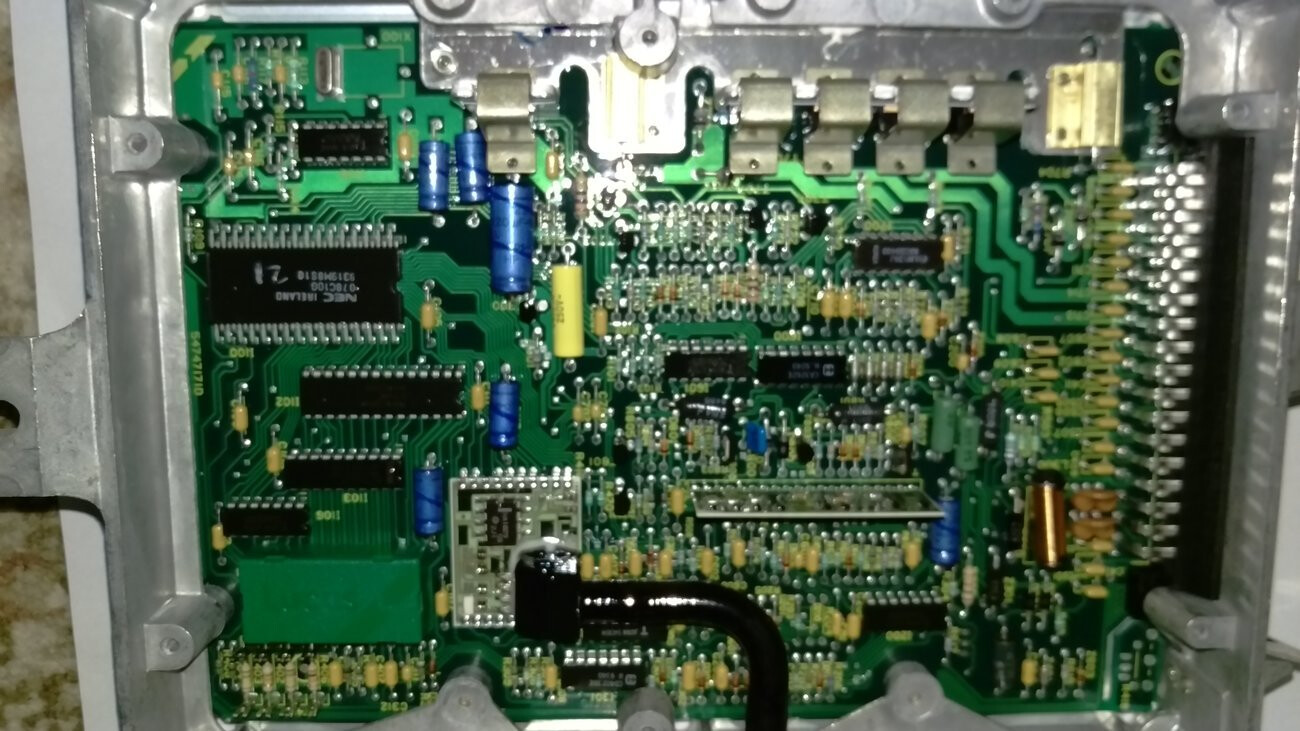
Here’s a 16CU using an NEC processor (enhanced… you can see the memory chip w/ references written on it)

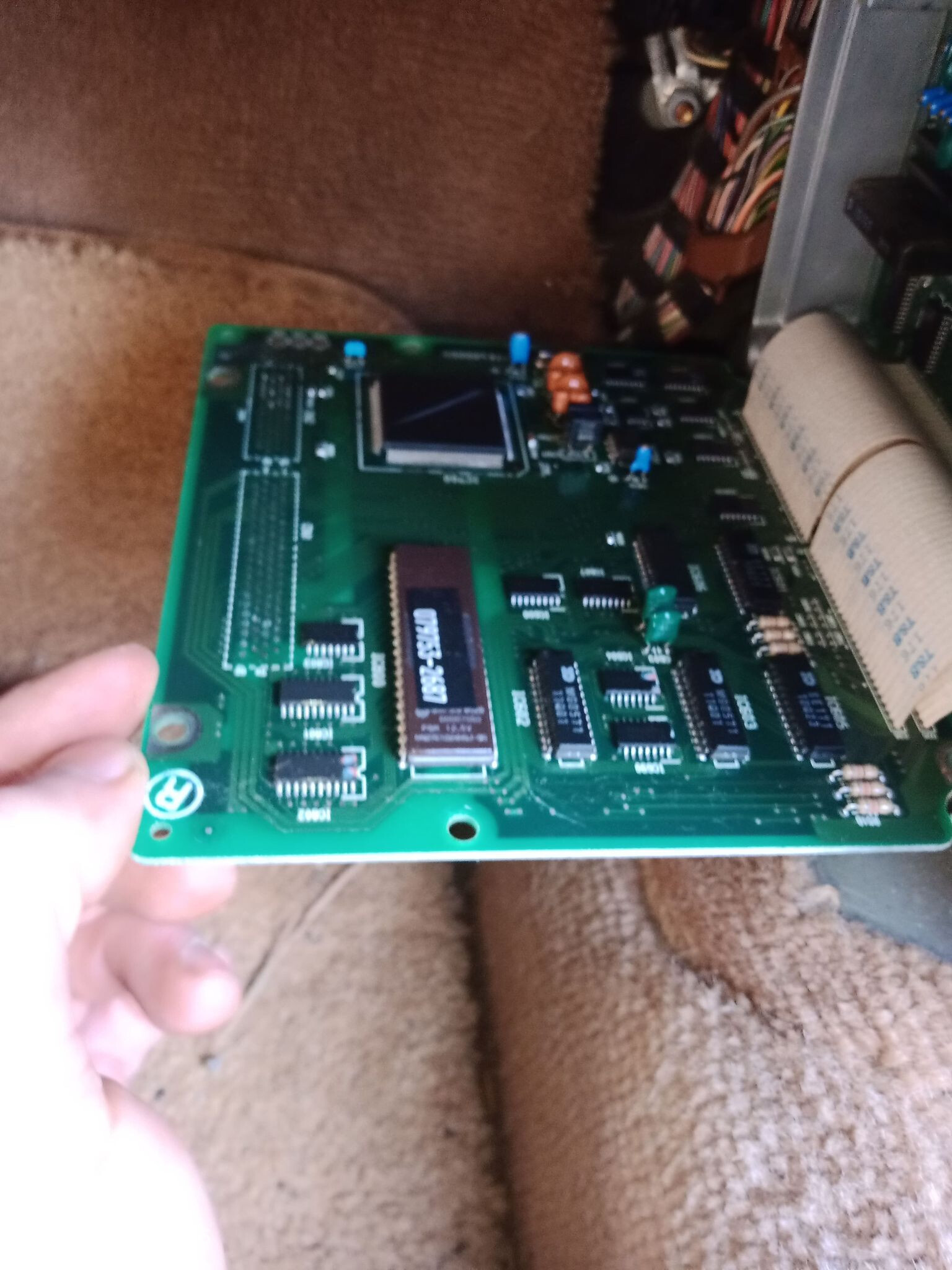
VS 26CU (slight pinout change)… also using an NEC processor - possibly newer
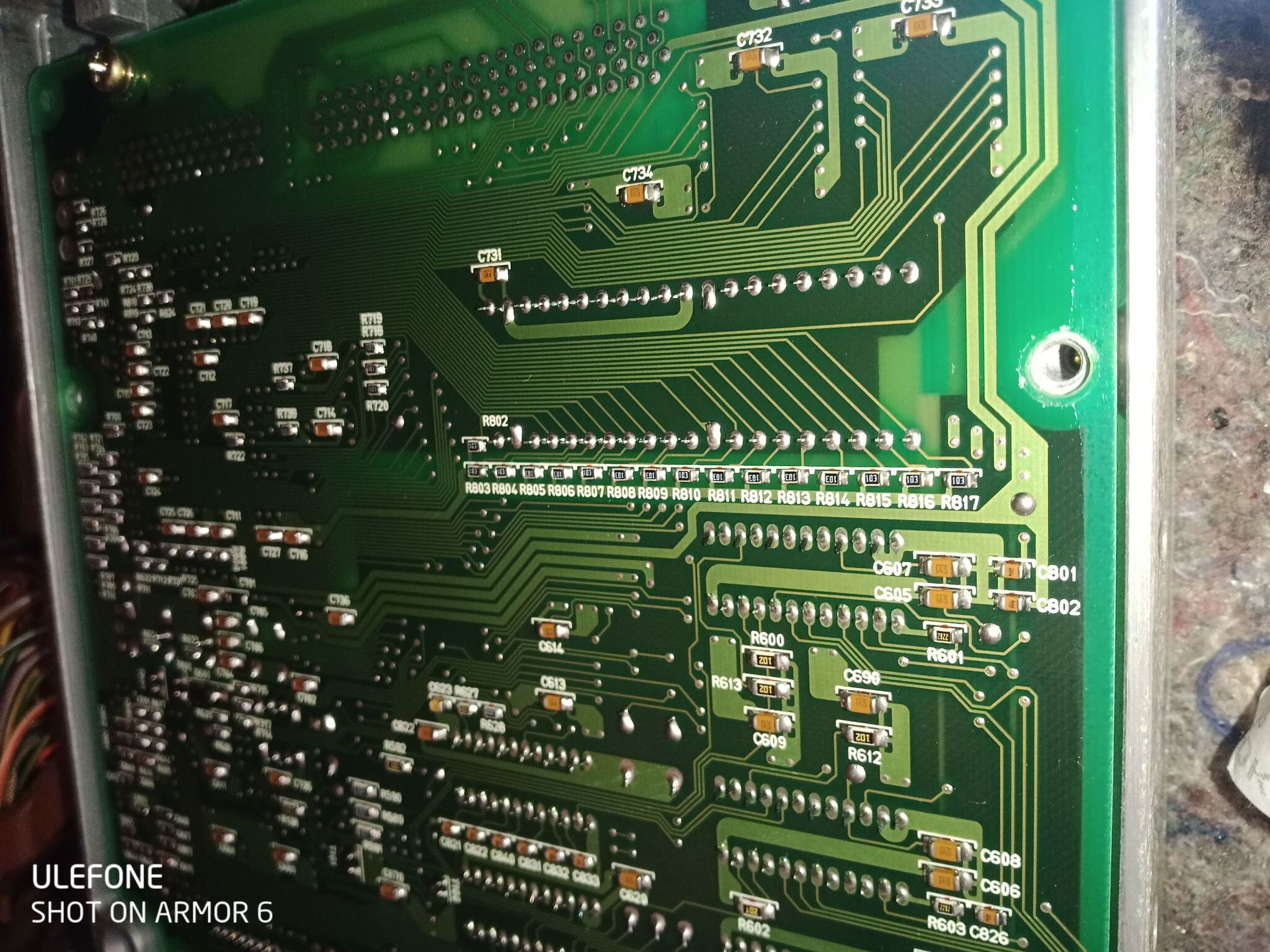
VS Yet again, the 36CU with another slight pinout change, but still the same design and NEC ECU family.
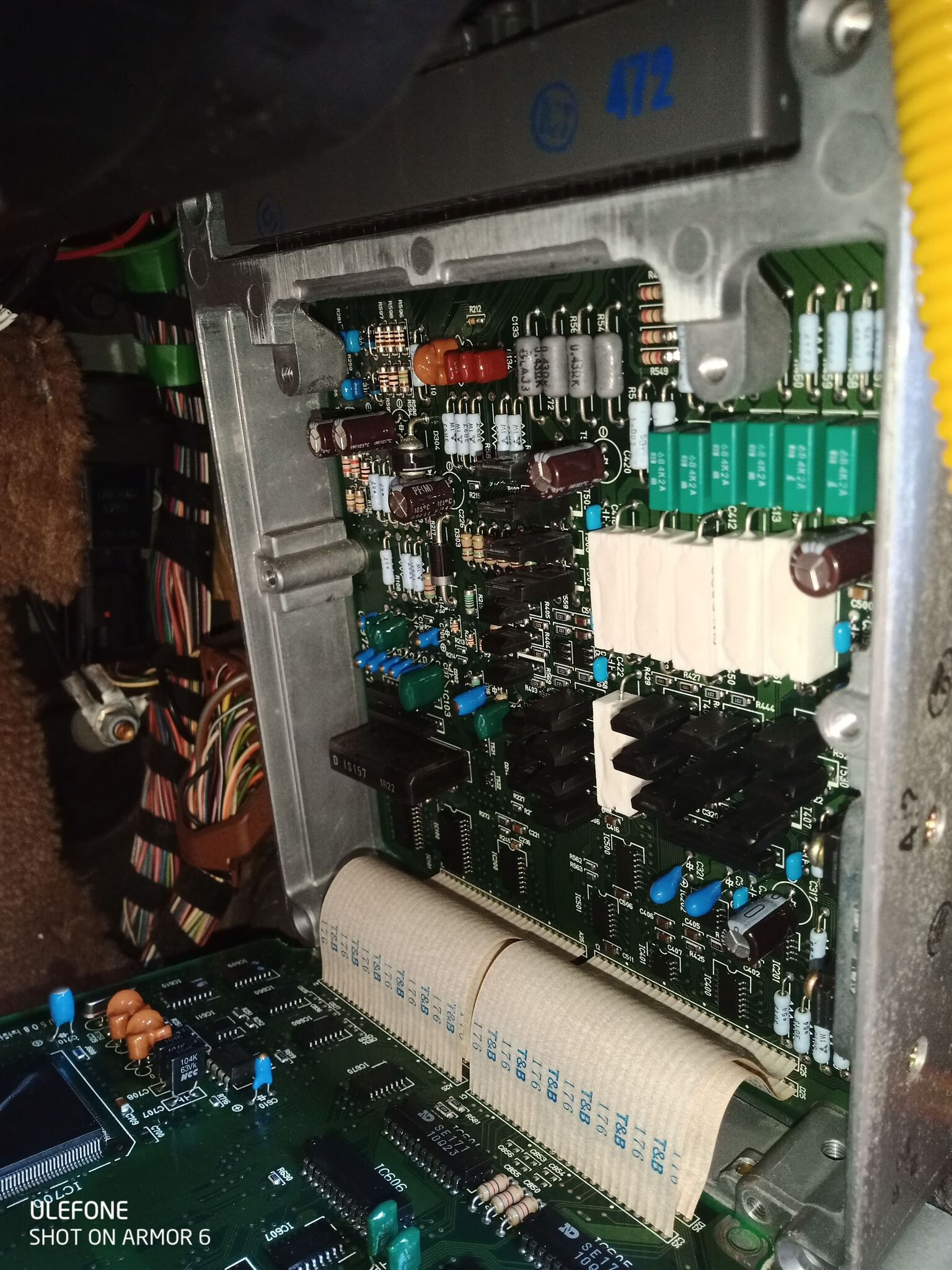
VS NipponDenso Box Internals with clearly only 2 heat slinked mosfets vs the 6 or so in the Lucas box.
More views of the Denso box:
By wiring diagram Denso System injectors are fired in pairs (semi sequentially as noted), whereas although in the Lucas system, although injectors are wired in 4 sets of 3, they’re actually fired in batch bank to bank as the channels are fused internally inside the Lucas ECU.
~Paul K.
It’s nice to see a summary of the fuel injection options Jaguar had for the v12. Together with the information on the Roger Bywater website, it covers the OEM setups from 1976 to 1997.
This does assume that the Bywater approach is taken, i.e. transplant an entire fuel injection system from a Jaguar v12 into the etype. There are two downsides to this. Firstly, you are buying 25 year old tech and the world has moved on a long way in that time. Secondly, the OEM setups didn’t allow the end user to alter any of the settings.
There are many aftermarket setups availble now and they offer considerably more flexibility in how the car will perform and how that performance can be analysed and measured.
Assuming you are looking at using the later 1992+ inlet manifolds, the differences between them are restricted to how the PCV system is plumbed in and what fittings were bolted on to the ends of the manifolds. The last incarnation saw a substantially beefed up PCV piping with two big tubes under the manifolds connected into the jackshaft cover. There is a Jaguar technical manual somewhere out there on the web explaining this. The fittings on the ends of the manifolds housed a large crossover pipe at one end and various vacuum tubes on the other end. If going for a modern mapped ignition system (rather than the complicated cocktail of solenoids and valves to control vacuum advance to the distributor) then much (all?) of this can be omitted.
My setup is run by a Megasquirt3 (“MS”). This runs 12 low impedance Jaguar injectors (1992-4 vintage) and 12 even lower impedance LPG injectors, both controlled by a peak and hold driver box which the MS controls. It also controls coilpack ignition, idle valves, fans, fuel pump, additional coolant sensors, exhaust gas temperature sensors and lambda sensors on each of the four downpipes. Most importantly, it datalogs all of the engine parameters, right down to waterflow to the radiator (and bypass) on both sides of the engine. It is all visible on a laptop in real time or as graphs and tables viewable later, so diagnosing faults is similar to having a new car. Even individual cylinders can be trimmed for fuel and ignition if so wanted or new peripheral components like extra MAP sensors can be added. This gives a much better insight into what is going on than simply fitting 25 year old components from an older already scrapped Jag v12. The downside to going with this approach is that it will necessitate learning new things, which many are unprepared for, but it is not really any different to fixing a carburettored car and learning about that instead.
kind regards
Marek
1992-4 inlet manifolds mated to 1971-4 airboxes. The “triple fuel rail” is the Jaguar petrol fuel rail and a custom LPG fuel rail sandwiching a conduit for the injector wiring.
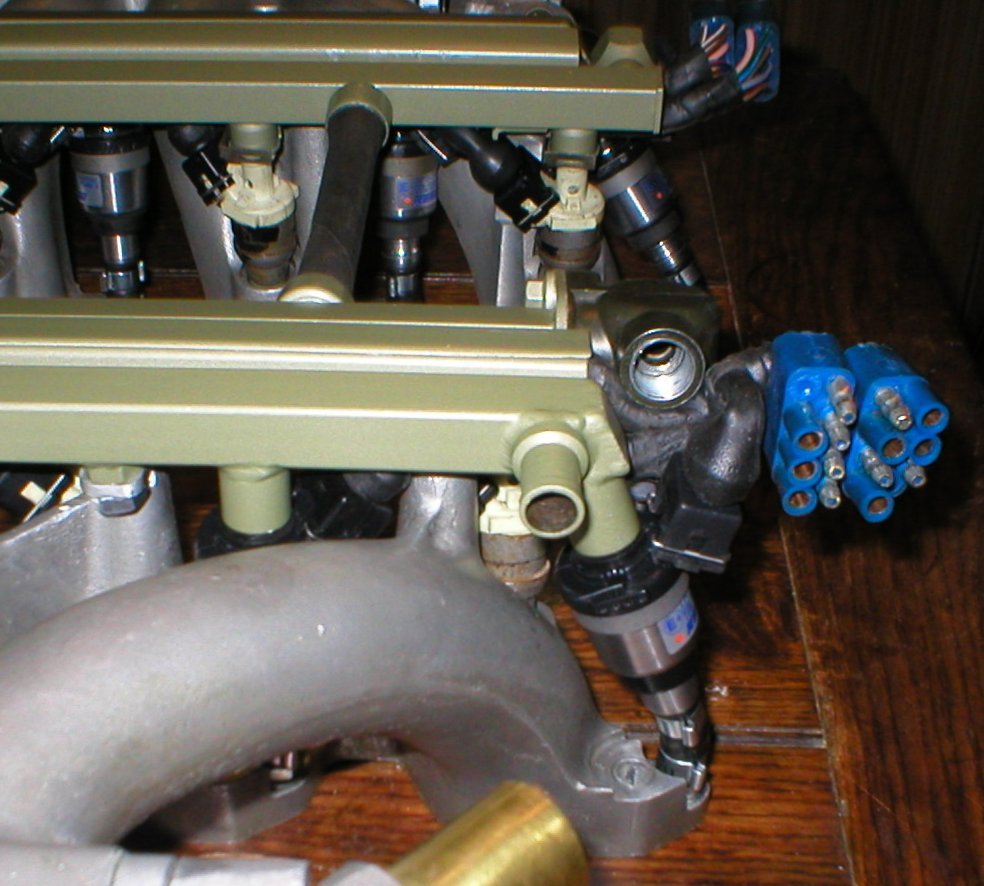
A closeup of the manifolds and how the injectors and their wiring dovetail.
Part of the electronics for the 24 injectors
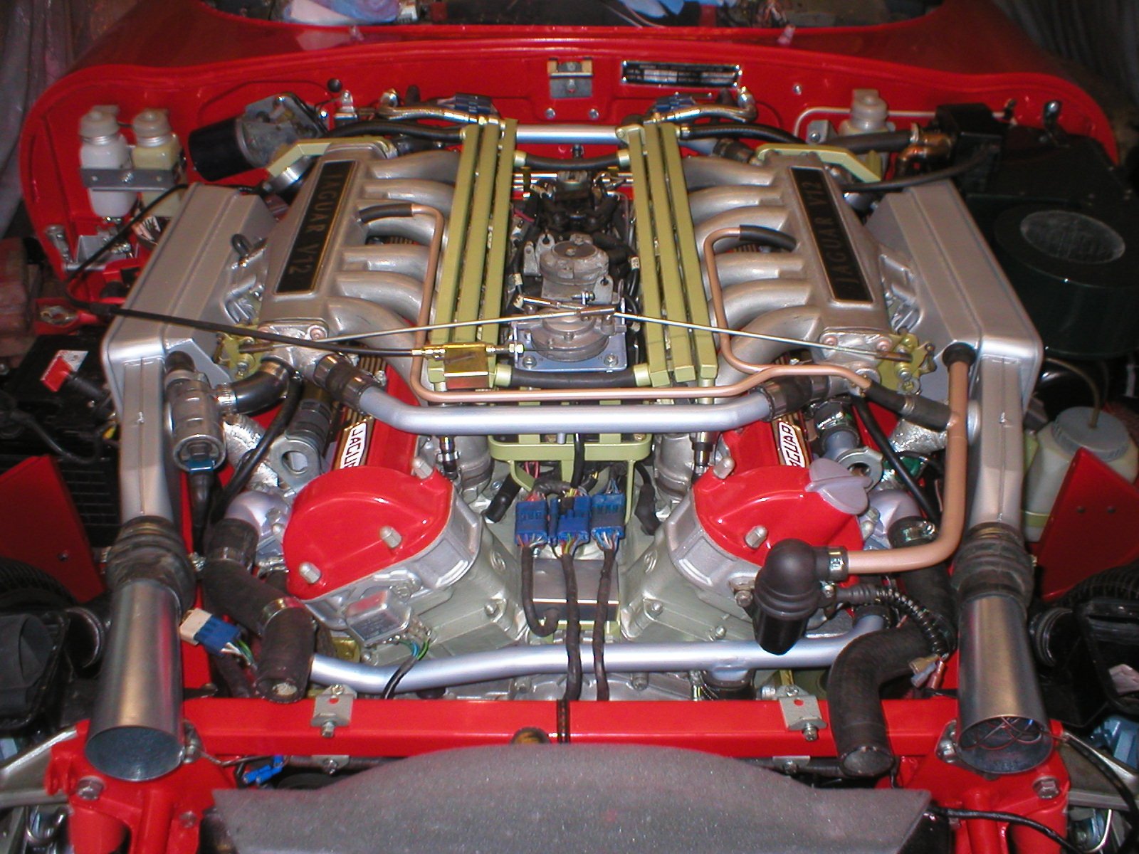
Engine showing new inlet manifolds with original airboxes altered to meet them
Marek, thanks for the pictures and your insights. You make a good point about the AJ6 approach vs something like MS. I’m interested in pursuing a MS platform but, being new to this type of endeavor, I’m finding all of the options a little confusing. Do you just buy a MS3 kit like this one to get started?
For a batch fired fuel injection, you can go with MS2 and read how Philip Lochner has put his cars together.
For sequential fuel injection, it’d be either a MS3 with a MS3X board with four extra drivers OR one of pre-built MS3 units.
Both Philip and myself post here and on the UK forum forum.etypeuk.com so there is plenty of background reading you can do. I am in the UK, near Guildford.
Other ECUs are also available.
The v3.0 board is just the bare basic circuit board. The processor is either a MS2 chip which sits on a plug-in daughterboard OR a MS3 board which plugs into the v3.0 board. The MS3X is a further board that plugs onto the MS3 and it has 8 injector drivers for high impedance injectors. The MS3X also has the ability to add four more inject or drivers so sequential fuel injection is possible.
If only running the MS2 processor, then the basic v3.0 board has two injector drivers which each can handle six injectors in parallel, so batch fired injection like the Lucas ECUs had is possible
If running the MS3 processor, these two “big” injector drivers on the v3.0 board aren’t available as the software uses the outputs as part of twelve sequential ones.
A v3.57 board is a pre built v3.0 board using surface mount components.
kind regards
Marek
I agree with Mark about the choice between an OEM ECU and aftermarket. There are limitations and pluses to both. With the OEM ECU you get near plug and play setup, but will need Rogers help for any variance / extra oopfh (which has a cost)… and you can’t reprogram it/adjust it yourself. And I’m not sure how well Roger has captured all his decades of experience as he slows down his business. With an aftermarket ECU you’ve got a bit of a range from DIY to commercial.
On the commercial side - there’s only one plug-and-play ECU currently available for the V12, from Ole Martin Mobeck in Norway. The system is costly, but for what it is, it is complete (new injectors/loom/etc) and pre-programmed (but adjustable). V12 efi kit % - mobeck.com
Others can vend Emerald ECUs, or Haltec etc… (expensive of course)
The DIY series of ECUs has a lower ECU cost barrier, but you have to do EVERYTHING yourself… or near so… sometimes from ECU assembly (soldering) to wiring to programming & tuning etc. Luckily with some of the more well known ones (Like Megasquirt) there are head-starts.
Having … partially done this myself… might I suggest to only get a full DIY kit IF… you’re comfortable soldering. I have my own aborted V12 Megasquirt 1 project from probably the second group buy from Bruce and Grippo (the guys who really pushed and started the DIY EFI ECU movement.) There are number of hours in soldering - and getting that technique right. Also, if you don’t buy pre-assembled, you’ll also need to buy or assemble a “JStim” which is an engine simulator to test your ECU you’ve built.
The advantage to MS is it probably has the most people with experience like Marek and as mentioned Phillip (maybe the first guy to do it?)…
But MS isn’t the ONLY system with folks with experience and it would be worth looking at two other exciting ECUs that are also known to be running Jag V12s, and both are largely pre-assembled … and also… nicely… use surface mount components unlike much of the MS system except the most recent preassembled units.
These are Speeduino out of New Zealand (really only workable to fire injectors in batch … which is still OK)… It’s a more simple ECU, but the guy coding it is really cool, and it has a large body of community support. The ECU is very small and professionally packaged (I think more so than the MS). There is at least one XJS V12 running this system. Home | Speeduino - Open, easy engine management
And RusEFI Proteus. Possibly the most advanced DIY board on the planet… and also around $460 bought 80% preassembled with a professional package/connectors. Also surface mount. Capable natively of sequential V12 injection and ignition without extras if I recall. There’s also the Frankenso which runs on the same base firmware. https://rusefi.com/
Both are open source code and hardware platforms with RusEFI being especially encouraging of new hardware configurations.
Megasquirt is a tried and true valid DIY box, but I encourage looking at the others to see what fits you best.
Also back on topic regarding the intakes, indeed the latter facelift intake is slightly larger runner wise (thinner casting w 2 or 3 extra MM inside on the runners), but do keep in mind if custom building a V12 for power, group A manifolds are now available from Donald Miles & his TWR/XJR15 parts re-creation business in the UK. These manifolds look just like the originally supplied pre-facelift ones, but are larger castings having internal runners that taper from 41mm to 36mm at the head. Facebook Groups Ole Martin Mobeck just built a TWR tribute car and used them on the spec-built engine he built for it and hit the Group A known HP target for the original engines.
https://www.facebook.com/twrtribute/
~Paul K.
Paul, this is very helpful information. Thanks so much!
Yes, thanks very kindly for the info, I had seen the inlet mani’s on FB but had lost the post. I asked Donald Miles there:
Will larger inlet manifolds make a difference if inlet valves and ports are unaltered?
Were “small” (~47% of bore Dia vs USA 50-52% of bore Dia) valves fitted due to the long connecting rod?
David Vizard says the valve - valve seat really controls at moderate lifts - would this be the first place to work before fitting an enlarged manifold?
Thanks very much for your kind response.
Wow this looks great. Lots of interesting modifications. I noticed you moved the throttle pedestal to the front of the engine.
Today I learned that the XJS throttle pedestal won’t bolt up to a carb V12 valley plate. The bolt pattern is slightly different and it appears that it has been rotated in the EFI cars. The carb pedestal leans forward whereas I think the EFI cars had the pedestal lean backwards.
Trying to figure out the quickest way to a throttle position sensor solution. Either extend the base of the EFI pedestal or modify the stock one.
Any thoughts?
My throttle pedestal top is mounted on four 5/16" studs bolted into the valley cover. I haven’t reused the main part of the tower.
kind regards
Marek
When I did my throttle pedestal cable modification years ago I think I used one of the turntables shown in your pic and mounted it on a 5mm ally plate I bent up that was bolted across the two intake manifolds, so no pedestal required. You can see in pic below
Can you mount a TPS on one of the throttle bodies? I figured if the Ford one on my HE ever packs up, that is where I will go, probably left side.