**
Have you looked behind the spare wheel, at the normal place for the motor, Tony - to see what original wires may be there?
Which may be the original set-up - and the wires on the, likely, aftermarket you have got may differ. Two basically different set-ups were used; one with a relay built into the motor - and one, like yours, with a separate 5-pin relay…
The motor, with two wires powered alternately from the relay - one wire powered for ‘up’ and one powered for ‘down’. One wire (nominally white/pink) on the relay is connected to the radio’s ‘ant out’ connection - which is powered (from the car’s white/pink circuit) when the radio is ‘on’ and unpowered with radio ‘off’. However, while the motor ground is motor body, connected to the car chassis by the mounting bolts - an extra ground wire may be used to ensure good ground connection…
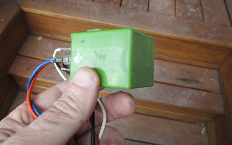
The relay has main power (from car’s brown circuit) - and should have an inline fuse. So the wire (red) in the picture with the inline fuse is likely main relay power. The relay also has a ground connection (usually black) for relay operation.
Operation; the relay’s unpowered position (radio ‘off’) connects to the motor’s ‘down’ wire - powering an extended antenna down. With the radio ‘on’, relay is energised and power is applied to the ‘up’ wire - extending the antenna.
To verify relay connections; a multimeter should show some resistance between two connections - the relay coil. White/pink (radio) and relay ground (car body). Unpowered: Two connections will show make - main power and antenna ‘down’ wires. Two connections will show ‘break’ - main power and antenna ‘up’ wires…
This leaves some of your wires/items in the picture unaccounted for. The green thing may indeed be a delay unit, though not necessarily related to antenna operation.
The ‘other’ wires may be some unknown/unused functions, but both the original and Aristides diagram indicates that they relate to ‘map light’, ‘clock’ and ‘boot light’.
The wiring then use the harness and unknown bits as convenient connection points for these items - which in principle should have constant power from fuse #3 or #13 ratter than the brown circuit…?
Again, looking for wires at the original motor placing may offer some clues - Jaguar usually installed wiring to cover all markets and optionals in all cars…
When sorted, sort of; test the system before fitting, of course - adding that there is a general warning to fully extend the antenna before retracting, and vice versa…
the “non green” one has a clear plastic case, and a metal tab to attach to body, which extends into the body of the relay…it definitely seems like that tab should be earthed.
I am hoping if I earth that relay tab, and the antenna motor body, that only leaves the question of the green wire, as the fused red one should accept 12V+ hopefully the antenna will stir
the red & green wires are the only control wires entering the relay
edit…+ to green should cause the mast to rise…remove 12v, retract…hopefully
Be careful, Tony - two wires only implies that it is not(!) a relay. I think some preparatory multimeter tests are called for…
You mentioned a 5-point relay - which is what is to be expected with the external relay set-up, and which function I described. With a built in relay; the motor itself has main power ‘in’, control wire from radio ‘ant out’ and possibly a ground wire…
XJ6 and XJ12 are the same…
The green reley is indeed a delay relay.
The mast will go up imediately when power is applied, but it will go down after some seconds when the power is removed.
I wonder why you have the second relay… it doesn’t make sense.
Also, if you don’t care about the delay feature you can substitute the green relay with a generic DPDT relay.
Just follow the schematic and it should work.
a brief description of what the green delay relay does in practice would be handy, to help work out how to test it, and whether I want to utilise that feature ?
I dont know how long the delay is, whether on up or down ? etc…ie cant find a description of its operation
Try the same connections but with a normal SPDT relay.
If it still doesn’t work then your antenna internal micro-switches, connections or motor are faulty.
If it works then your green relay could be faulty.
**
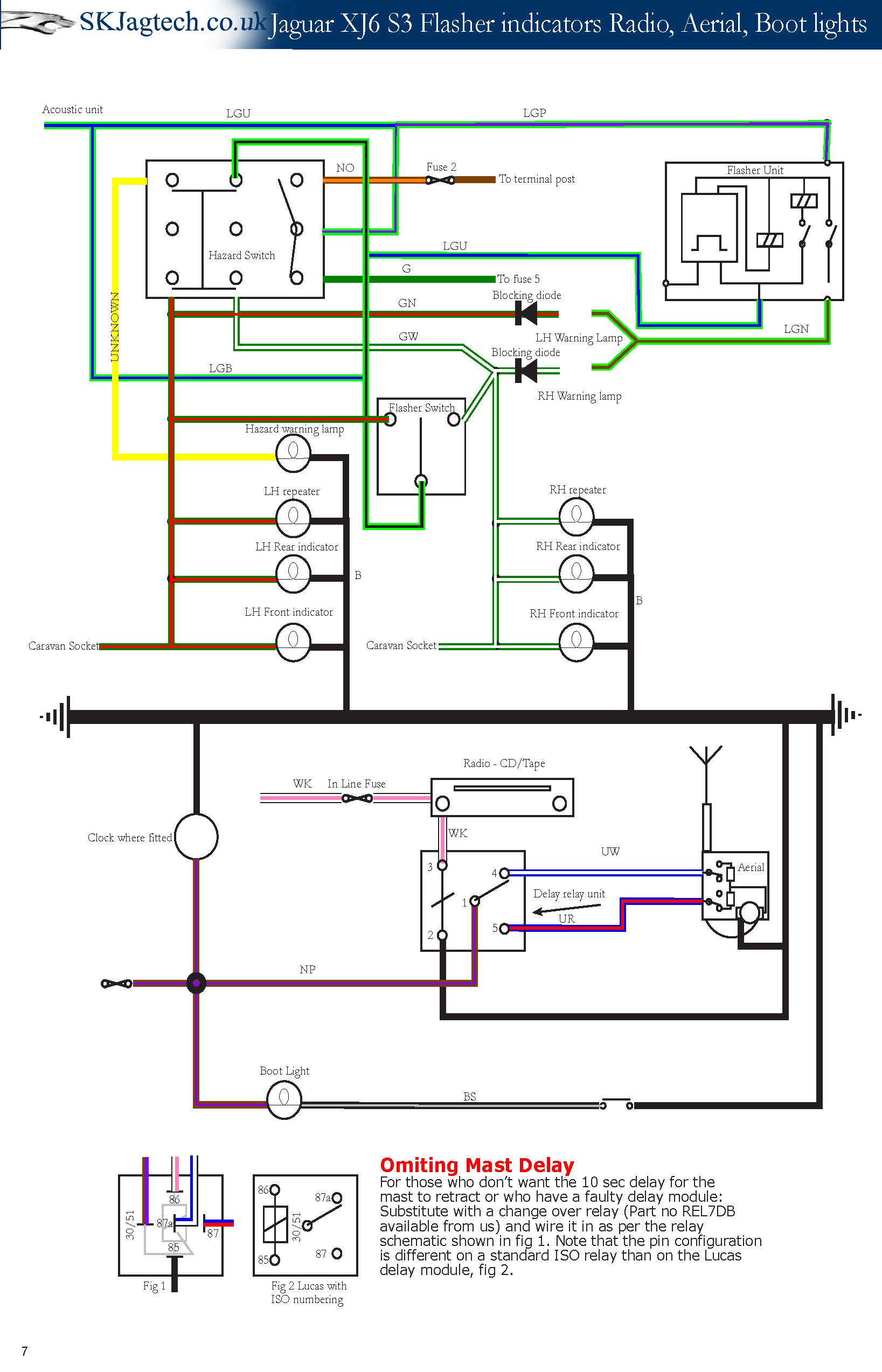
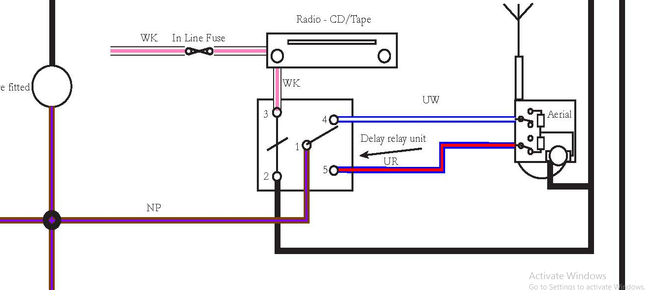
Where did you get the schematic for the ‘delay’ unit, Tony…? It actually shows the layout of the ant relay - the original delay relay use 4 connections. #1/2 is the delay action relay coil function - #1 connected to permanent power. The #3/4 basically grounds the interior lights when the relay operates - #5 is not used…
The green delay relay is not related to the antenna motor, and is not connected to it - or to the radio. The delay unit is basically meant for the interior lights - and the purpose is to delay turning off the interior lights some 10 -15 seconds after opening a door…
To test green delay unit; connect #1 to +12V, and #3 to ground (-12V) - and connect a test lamp between #1 and #4 (simulating interior lights). The test lamp should be unlit. Ground # 2, simulating an open door; the test lamp should light up for 10 - 15 second - turn off.
This is how I interpret the original wiring diagram - and if confirmed by test lamp reaction; I am right…
You then have the wiring loom for the original set-up, but relevant wires must be connected properly to the car’s wiring to work the interior lights as intended. Which you may or may not want…
But if the antenna works as it should with the antenna relay connected - you may just leave the other wires insulated and not connected…
The wiring diagram I used is the one kindly supplied by Aristides, (expanded above)
…it says “delay relay” on the diagram.
The green one was hanging off the wire harness, only with an earth wire.
The antenna motor has a clear plastic relay that controls it, and works as expected
So I was sure you would be spot on, as I know you have been good with relays in the past,
but alas, when wired as you described, it does nothing
the green relay has the terminals numbered 1-5, so there can be no mistake there
maybe there is some way to wire it into the antenna relay circuit so it does its thing, but I cant puzzle it out
**
Whatever the diagram says; it shows the antenna relay, Tony…
The delay relay is completely irrelevant for the antenna control, and is not connected to the antenna motor. And since the antenna works as it should the green delay relay is irrelevant…
Ie; wiring the delay relay into the antenna control seems pointless - when do you want the antenna to stay up for 10 seconds after turning off the radio or turning off the ignition? It can possibly be done - but why…
The numbering of ‘special’ relays’ terminals are not necessarily standard - my assumption was that your ‘green’ was configured like the original. That suggested connections failed to operate indicates that this is not the case - but a complicating element that an external diode is required to ensure proper function with the harness is powered.
Ohming a relay, unpowered; between the two relay coil connections you read a high resistance - identifying those two. Ohm the others in pairs; one will show continuity (‘0’) - connected with the relay unpowered, default position. Other pairs may/will show continuity with the relay powered…
The specifics a delay relay is that when the relay coil ground (usually) is broken, the relay will stay ‘on’ (the ‘powered’ continuity between the connections) for the specified delay interval…
Original; #1 and #2 - relay coil with the delay feature. #1 always powered, #2 grounded through door switches (door open) with a blocking diode in between relay and ground. #3 and #4; default ‘break’ - #3 to permanent ground…
Interior lamps connected between #1 and #4; powered from #1 and no ground at #3 - no light. Door open; #2 grounded, operating the relay - #3 and #4 connected, grounding the lamps, which lights up.
Closing door; #2 loses ground, but the relay delays breaking #3 and #4 connections - the lamps stays lit for 10 seconds (or whatever).
All this is purely academic, delay is irrelevant for antenna control…
No, the green relay is the antenna delay relay Frank… identical to mine (SIII) mounted at the trunk by the antenna motor.
My car didn’t have a interior lights delay, so I don’t know for sure what the original would be, but IIRC it’s blue.
**
But what does the antenna actually do, Aristides; does it delay its extension/retraction - and why…
As said; originally the delay was for the interior lights - and the delay was integrated in the wiring loom to add the delay feature to the interior lights…?