Whuf! Long time since posting.
The diag stuff would be relevant to XJRS owners. Over on the FBook XJRS/TWR owners page we’ve got a running daig going of some XJRS problems and speculation about the boxes/replicating the Zytek interface very much as suggested above.

The RX/TX pins on the XJRS ECM are fairly easy to identify in pub S80 I think. They can ONLY be JSC4-9 and JSC4-6 on the round plug (Pin 10 and pin 29 on the ECM) because all the other wires look like grounds or signal grounds - except for the +12V supply split off to the ECM. The red wire needs to be tested as the diagram makes that one a bit confusing.
Pin 10 on the ECM is IDed as Output Diagnostic Connector 0.670V TX?
And pin 29 is IDed as Input Diagnostic Connector 5V RX?
Admittedly there is something confusing about the diagram as pin 30 is described as 5V Input the same way as pin 29, but if you trace that (red wire to JSC4-3,& 5) the diagram suggest it’s connected to signal ground shield wires - which doesn’t make sense to me.
Either way you’ve got a good idea of what’s TX and RX there.
The next thing that’s needed is some kind person with the interface cable to take an Ohm meter and test the pin-continuity on both sides of the cable so that there’s a diagram for re-making that cable pinout as it connects IN to the interface box.
Duplicating the box is the troublesome bit because they’re unobtainium and stupid expensive. OBDI interface designs of contemporary manufacturers were pretty dead simple though. A few resistors and transistors to invert a signal maybe, or combine RX/TX lines. Maybe a RS232 chip, or a 555 timer. Basic stuff. One can make a mid 90’s GM OBD1 cable with a resistor, diode, and FDTI USB cable.
Maybe if an owner had a buddy at an airport one might be able to examine it via X Ray 3d backscatter teck, or use a CT scanner on it.
The pins could probably be Ohmed w/ little risk to see if there’s a resistor involved…
A modern mid priced oscilloscope could record the RX/TX conversation out of one during a diag session and that would go VERY far in knowing backwards engineering the thing (baud rate / line levels / need to invert signal / if there’s anything that translates a signal in the box (unlikely I think.) Compare inputs and outputs and that should do it. The thing that the box MIGHT do is differentiate between ECMs and communicated differently depending on what it’s plugged into.
Harsher still, and risky, would be to de-pot the thing by putting it in near boiling water and going at any epoxy mechanically (which would usually become rubbery and break away)… but I doubt many box owners are going to allow that to happen.
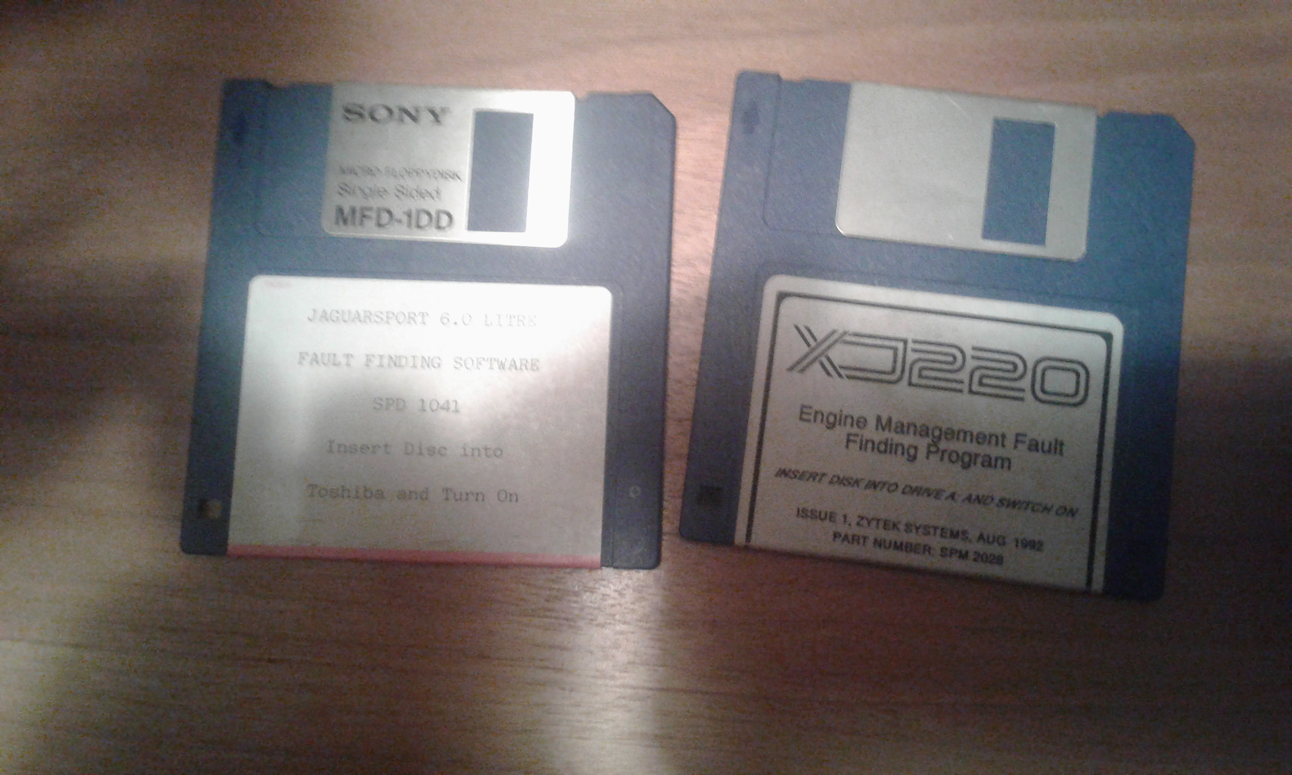
It would also be nice if both the XJRS and XJ220 floppies could be duplicated via WinImage as *.img files so that access to that SW wasn’t so $$$. Those that still have copies are reasonably interested in getting top dollar for their stuff though. I know of one person who claims to have a floppy (XJ220 & XJRS) set with diag box & cables gathering dust, and I’ll post about that probably on the XJRS & XJ220 facebook pages if the Coventry Foundation isn’t able to obtain them, and if he hasn’t already disposed of them to a new owner.
~Paul Kobres