First gen RX7’s are very similar, no idea if it would work.
And this dumb Jeep one is interesting as it attaches from the top
u-Box for Jeep Dead Pedal Left Side Foot Rest Metal Kick Panel for Jeep Wrangler JL & Gladiator JT 2018-2023 Amazon.com
First gen RX7’s are very similar, no idea if it would work.
And this dumb Jeep one is interesting as it attaches from the top
u-Box for Jeep Dead Pedal Left Side Foot Rest Metal Kick Panel for Jeep Wrangler JL & Gladiator JT 2018-2023 Amazon.com
If no one responded, I was gonna eyeball the angle of the brake and clutch pedal and use that as a starting point.
I have the RTC 9014 Parts catalogue and the image of BD39516 on page 28.38 is next to useless when trying to orient the Jag Foot Rest. Until @Dick_Wells posted the reference, I NEVER would have guessed the function of that “thing”.
I also refer to the Repair Operations Manual regularly and find no reference to a foot rest, dead pedal, 4th pedal or any other term for “it”. I looked in Body, Brakes, and Clutch section to no avail.
Which manual shows the orientation of the stock Foot Rest, please?
Sorry Craig I used the manuals to help me fabricate the part not for the placement in the footwell, that was pretty much what suited me.
Ahhh - the scaled have fallen from my eyes. Thank you.
@angelw posted this back on/about 03MAY23.
I dealt with the non-functional lift and did some adulting in my yard – finally got around to trying it.
I think it is bad news.
By now you know I’ll post a photo at the drop of a hat, so let’s ensure I followed Bill’s instructions properly. Captions = Details
Frank - the issue I’m dealing with (see above posting) has consumed my attention. I can’t add any restored bits on the block in anticipation of just needing to remove them if I gotta pull the head to deal with the stripped threads.
Similarly. I didn’t wanna start anything major (pulling apart and rewriting the gauge panel; trying to reassemble the E-Brake handle; re-assembling the heater box with new matrix and hardware; etc) cuz I didn’t want new stacks of bits and parts on my benches.
The mechanic I am relying on to help with the studs is dealing with issues of his own so I am treading water on anything right now.
I have been trying make small advancements so as to not feel totally useless. Mostly blasting and painting things; adding small bits back on the car here and there; installing fresh air ducting.
Some happy snaps just cuz
/
/
Hello Craig,
The part of the above comment, “that my dowel is just a smidge too thick” implies that the end of the dowel isn’t entering the Threaded Hole in the block, but the pictures of the stain on the dowel seems to tell another story. To ensure that the end of the dowel is actually entering the Threaded Hole for a sufficient length to take an impression, measure down from the top face of the Head at the stud hole, to the face of the Block and mark that length on your dowl, then make another mark on the dowel, say one inch up from the first mark. In use, you should see the first mark align with the top face of the Head, with the second mark clear by one inch, then see this second mark get closer to the head as you screw it in. If there is a Thread there and you find it difficult to screw the dowel material you have into the Threaded Hole, use a dowel made from Balsa Wood. Although technically a hard wood, its actually quite soft and will take an impression very easily.
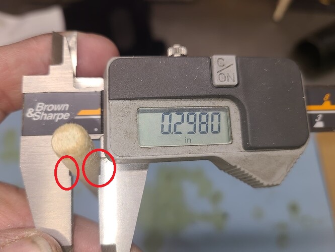
However, given that the pictures are a true indication of how you use digital, or vernier calipers, the next lesson needs to be on the use of this measuring device. You use the part of the caliper blades that come into intimate contact when full closed and where the digital calipers can be set to Zero and where Vernier calipers will read Zero, and not the relieved area of the jaws as shown in the following picture. That will for certain, have the part measure smaller than it actually is. ![]()
Regards,
Bill
Very, very beautiful, Craig. Better than new.
Very nice, indeed.
Frank.
Shame on me – I know better.
I’ll get more accurate readings tomorrow
Craig
Another lesson is that whenever we post pictures of ourselves actually doing something, there is a very high probability that we are doing it wrong. ![]() Hang in there, there are no mechanical things that cannot be fixed with time and money. In this case I hope it is mostly just a loss of time and not too expensive a fix.
Hang in there, there are no mechanical things that cannot be fixed with time and money. In this case I hope it is mostly just a loss of time and not too expensive a fix.
Rod
Really like the duct fans! How and where are you going to going to connect to a on/off switch?
Molly
As you saw on the data plate, both fans are 12Volts. Each fan has a ~6" attached pigtail power lead that connects to a much longer power cord with a110v prongs.
Do you think that will work? Automotive electronics is not my strong suit - I’m open to comments or improvements.
As we spoke of before, that’s just fine: the absolute worst you might have to do is to have the switch operatea a relay and wire the fans to the relay itself.
How about a (fused) relay, powered as you suggest, but then from a direct 12V battery cable? I think that your direct solution will work, but also sense that although max 4-6 Amps per fan, it may be a lot for a demister switch, because the consume more current when they power up than their rating…
EDIT: I correct myself. Your fan rating is 18W, that is about 1.5 Amps, so close to nothing, even on start up.
@angelw - here are better measurements of the hole, the dowel and the stud.
I think I need to take off a little more from the tapered end of the dowel to get a reading; but how much? This is my second try at taking am impression of the damaged threads - the taper on my first effort was tooo much; the dowel slipped right passed the thread and bottomed out in the hole .
What say you?
Captions
Hello Craig,
Yes, it wouldn’t hurt. In your case, either you have a stripped hole, or the Thread for a HeliCoil (or the like), in which case, your dowel should go in quite easily and may not take any impression. If in the case I was trying to determine the Lead of a Thread that I knew was in good condition, I would cut the diameter of the dowel I was using to be a bit above the Minor Diameter of the Thread and use that. The reason is that the Thread on the Dowel won’t be cut but pressed into the material. If the Dowel is made the Major Diameter of the Thread, the material being displaced by the Female Thread making an impression, has nowhere to go and you run the chance of breaking the dowel off in the Threaded Hole.
Cut the Dowel to say 1mm above the Minor Diameter of the Thread and try it. If no impression, go up a bit in size until you start to get an impression. If the diameter of Dowel is greater than the Major Diameter of the Thread before you start to get an impression, then you will know that you have the Thread for a Thread Insert or HeliCoil. If no impression, then you have a stripped Thread.
Regards,
Bill
Today I continued installing the fresh air venting system on the Series III - installation of the black plastic vents that opens/closes off air flowing into the foot wells or the windshield.
Doesn’t look like much but it took 3+ hours to get here. Too much time spent scrunched up in the foot wells and reaching over my head to get to screw heads.
Coupla less pieces laying about.
Concluding Comments
This question is for @Dae_Bennett or any other Listers who have installed the dead pedal from a 89-91 Mazda Rx-7. I received mine the other day and have cleaned/painted it.
My question is: “Can I assume that angle of installation is implied by the pre-set manufactured angle?”
In order words - will the two holes I’ll drill into the inner sill parallel to the floor pan?
And I assume that the distance into the footwell toward the front of the car is driven (pun intended) by the length of my leg / by my comfort level?
Bill
Preface - some measurements of the dowel and stud in mm’s so we are talking the language.
10.29mm - Diameter of Hole
8.27mm - Minor Diameter of the 1.5 threads already pressed into the tip of the dowel (~2.4mm from tip)
9.44mm - Diameter 15mm from tip of the dowel
9.90mm - Diameter 30mm from tip of the dowel
10.09mm - Diameter 40mm from tip of the dowel
9.30mm - Diameter (major) of stud
8.25mm - Diameter (minor) of stud
23.0mm - length of coarse threads cut into the tip of the dowel
If I understand your instructions correctly, I currently have 1.19mm difference (9.44mm - 8.25mm) between the minor diameter of the stud and the diameter of my dowel about 15mm from the tip.
Is that close enough for you to make an assessment? I’m not sure my left palm is calibrated to a sufficient degree of accuracy to squeeze 50 grit sand paper properly to remove ~0.2mm of soft pine - I can certainly try.


