Was the poor woman left with any scars?
2 Likes


Here’s an easy one…
So if your steering wheel is loose in and out just a bit and the collar is tight
Always check the steering wheel bolt
Mine was loose and once I tightened it everything was solid again!
I will do the column and bushes one day but that trick makes the car feel
New!
Gtjoey1314

Sorry guys no posts today
I need a day of rest as my fingers are swollen from the small detail work
I’m watching Marriage Italian Style!
Ahhhhhh Que Bella!
Gtjoey1314
2 Likes
Well, I ordered the HT starter, more gages on the way and the rest of the led lights should be here today.
I ordered the rubber jag mats which were always great and new plugs for the carpet.
Will have pictures soon.
The Dayton/grainger motor with a permenant magnet draws a lot less then the original winding motor for the heater blower.
In turn it also blows a lot quieter.
Pics soon.
gtjoey1314
1 Like
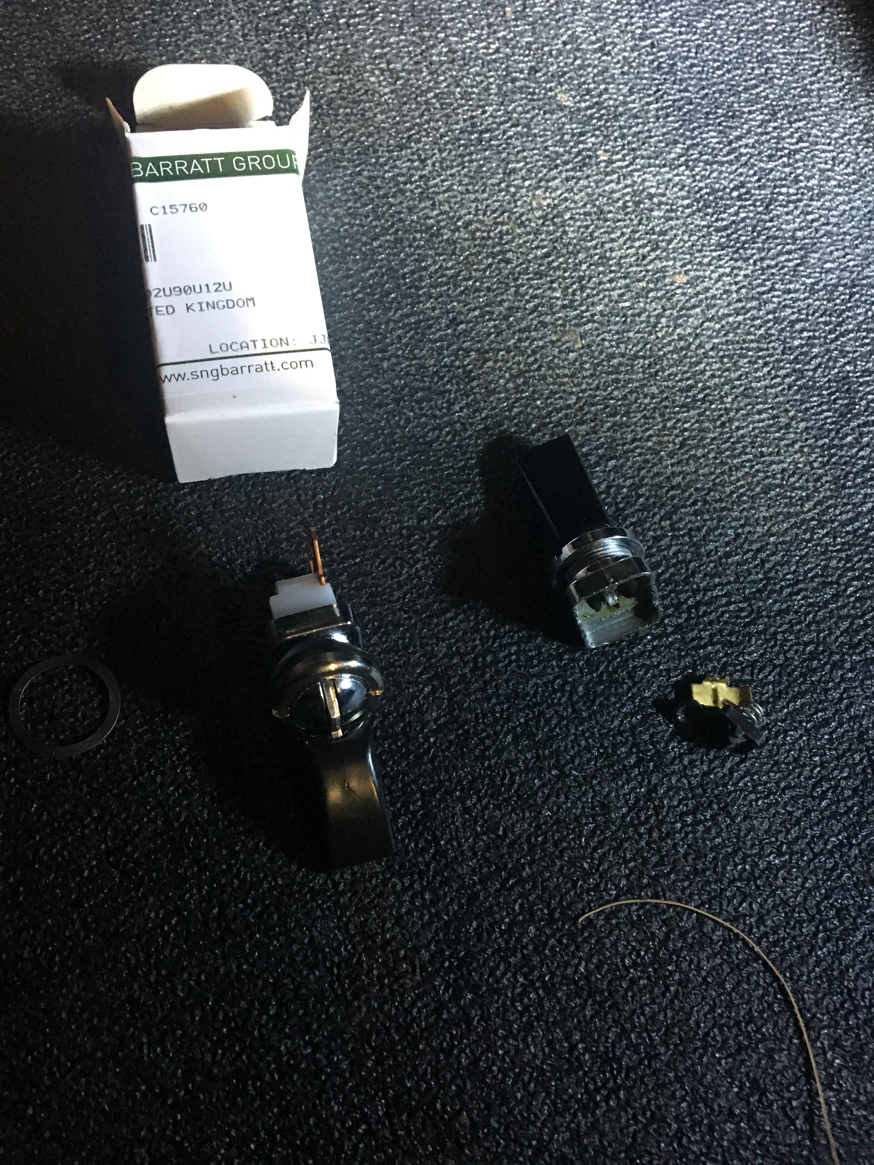
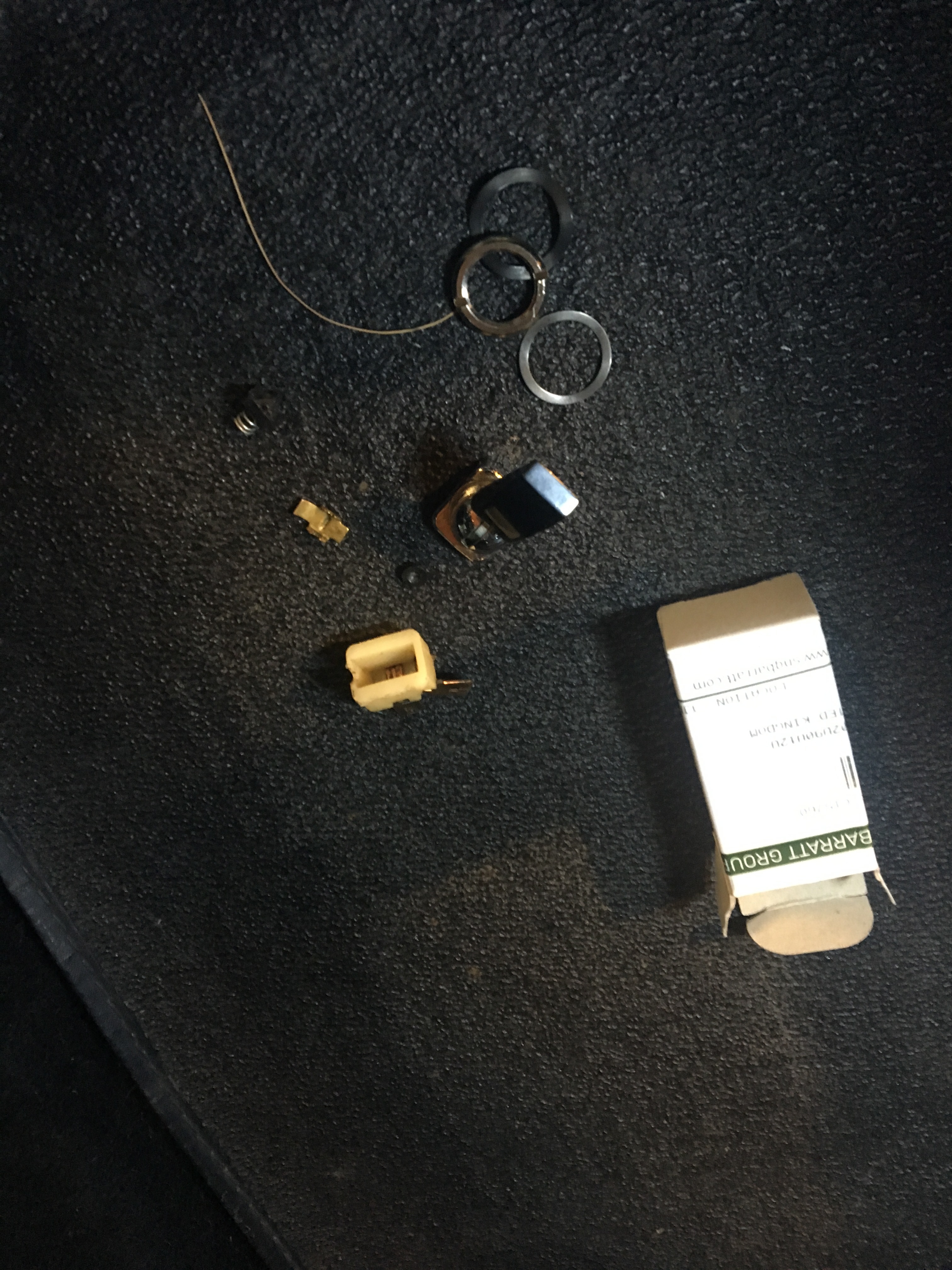

I installed the led interior lights
They started to flicker which is impossible
I opened the dash and the toggle just fell apart
Sng has them for around 25 dollars!
I used the original chrome ring instead of the new stainless to match the rest of the dash
The light is the perfect hue and now uses less than 1 amp and can’t melt the cover!
Gtjoey
The map light is done as well
A hair clearer white light but the effect is so modern yet clean light
Not over powering
Just wait till you see the complete dash!
I compare it to a db9 very very good looking!
Gtjoey1314

Okay lets hit the “THIRD RAIL” with the group when it comes to wiring and safety.
On my EALIER cars such as DB2 or XK120 , They all have the same basic set up with all the current and wires running THROUGH the light switch with really no fuse system.
Many years ago people smarter than me came up with a BOSCH RELAY as the feed to the switch and also moved many wires from the one set screw to a more secure relay .
This did two things, It isolated and made a breaker for the switch .
This way a short would not burn down the whole car and isolate the lights away from everything else.
OLD SCHOOL.
I received two calls from friends over seas doing the same with the ETYPE wih the same old light switch on a series 1.
Its fused at the block , do you think its overkill?
Need some input…I like the idea, but don’t want this to turn into an xj6 series 3 with 3 fuses in a wiper motor circuit:)
gtjoey1314
thoughts.
Anything that takes current from switches has to be a good thing, I can remember how hot my ignition switch used to get after a night run using the lights in my ‘S’
I am certainly going to place relays in the circuit when I redo the wiring for my current ‘65 ‘S’
2 Likes
HEATER BOX…
Well, I just got off the phone with SNG , The reproduction blower motor is a permanent magnet and only draws 1.3 amps!
Compared to the original at 3+ to 5 amps and the old windings making friction.
This is another way to go.
Yes I see the fiero kit but I don’t want to cut the box.
The squirrel wheel is a new pitch and a hair larger, so lets see what it does…
I have news for all real soon about the new book so stay tuned.
Robin, I agree, , its an interesting balance of safety, technology and applying something to an old formula AND MAKING IT WORK!
Its really fun compared to my first build 30 years ago, this is a different challenge.
Thanks for the input.
GTJOEY1314
GTJOEY1314
The headlights on my TR6 appear to be wired about the same way as the E. I used a headlight kit from http://www.advanceautowire.com/.
It was a very clean install and the headlights were much brighter than without the relays and fuses. It was very easy to hide the block and run the wires along side existing. Looking at the car you cannot tell the lighting has been upgraded. No affiliation, just a very satisfied customer.
Gordon
1 Like
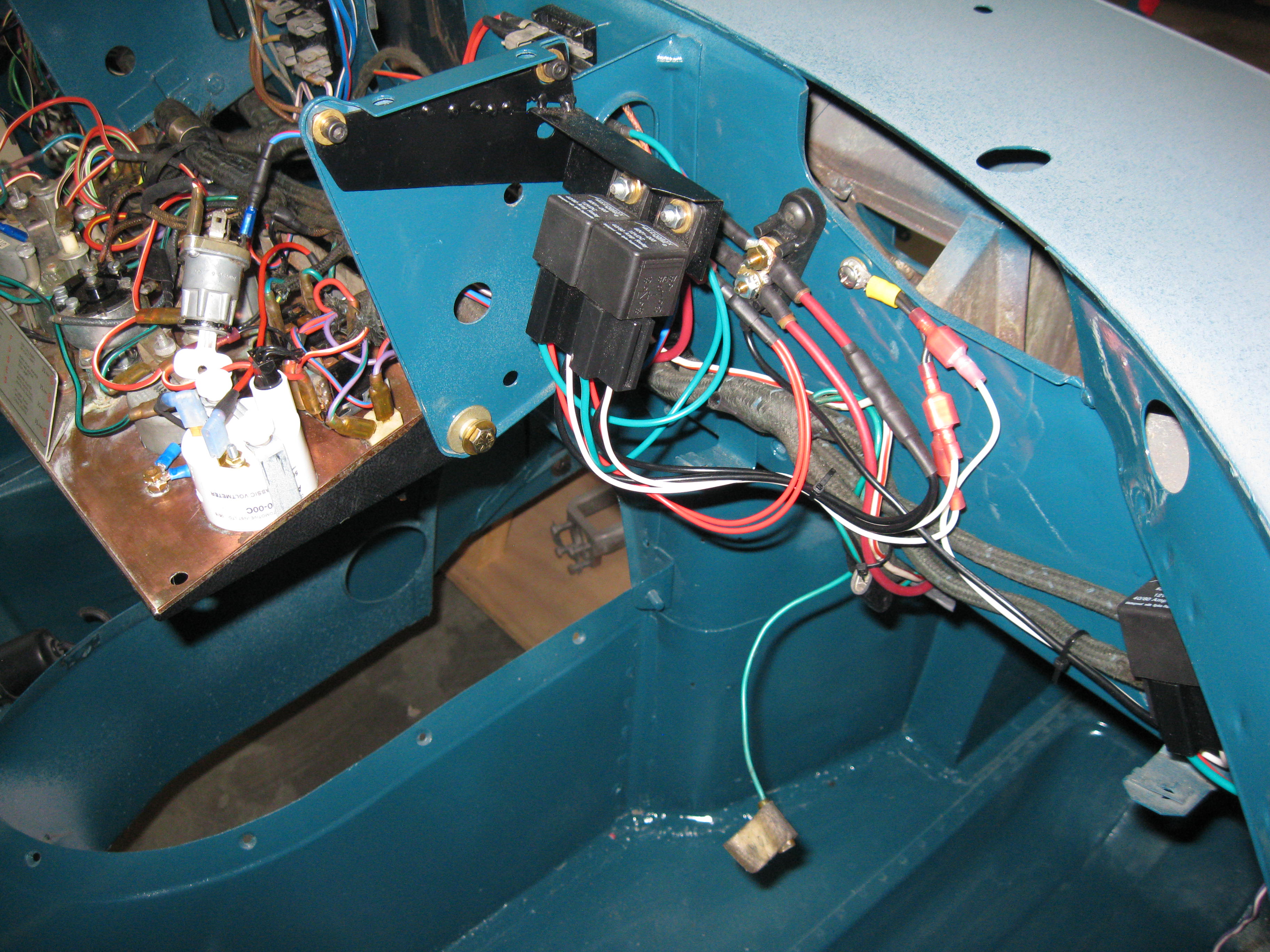
If you’re serious about installing an AC system in the future, you might want to start rethinking the entire electrical system from the ground up, as opposed to making willy nilly upgrades to this circuit, and then that circuit, and then the next one. I mentioned the Bob Skelly electrical system upgrade early in this thread. It’s a comprehensive makeover of the electrical system using the existing wiring looms plus a few additional wires here and there, plus modern relayand fuse panels. But the big change is from an architecture perspective. It segregates switched and unswitched circuits, adds 30A modern mini-relays to high load circuits, and completely offloads the ignition switch. I took Bob’s concept a little farther…here’s a photo of the electrical distribution center. There’s another small panel hidden behind the glove box (false rear panel). There are ten relays in the system, and two new fuse panels with modern bayonet type fuses. If you want an air conditioned car with a bullet proof electrical system, this is something to give serious consideration. Forum member larebob has done something similar. I was converting to an alternator, so used the old voltage regulator location for the distribution center. The original looms still reside in original locations, but most of the panel switches now simply control the switching signal to a relay. You can have hidden relays stashed all over the car, or just make a clean change from the gitgo
The battery cable goes to the insulated terminal post (as do the alternator and starter cables). Also attached to the terminal post are two large red wires that feed two 40 amp fuses…the two black boxes at the top of the stack…one for switched (by the key) circuits, and one for unswitched (hot circuits). There are two large red wires coming out the other end of the fuses which feed…hot and switched loads. The second tier of the stack are the mini relays from Waytec electrical. They gang together for compactness. The lower box is a large fuse panel with mini fuses. The panel behind the glove box feeds the starter and electronic ignition circuits and a few miscellaneous items like the brake warning system.
This would be down the road stuff for when you pull the engine and install the AC. But again, now is the time to plan for it.

1 Like
Nice set-up: any close-up pix?
Now your talking………I get the main power source then the feeds…
On closer inspection is the alt and a/c on a serpentine setup?
Thanks…
Moving on, I went to replace the squirter rubber gaskets and the repros were junk, They just fell off and had no give.
Off to the hardware store and will post pictures…
The water gage will be here, leaving just the amm to go.
Thanks everyone.
GTJOEY1314
The AC belt is a large section serpentine V-belt. I’d prefer a modern flat belt, but this one works.
If you decide to revamp your electrical system at a later date contact me and I’ll send you a copy of the new wiring diagram. It’s currently in draft form. By the way, the ammeter is bypassed in this configuration making a voltmeter conversion simple. There are relays for hi beam, low beam, parking/instrument lights, radiator fan (two relays…one for Otter switch activation and one for AC activation…same as S2 with AC), heater fan hi and low, horn, starter and electronic ignition. The AC power is on a kit provided circuit breaker. The wipers stay on the fused switch, primarily because two more relays take up more space and the load is not all that high, rarely activated, and then only when alternator loads from the AC are probably low (raining). That said, it’s easy enough to relay that as well with this system architecture. The instrument lights are wired to the parking light switch position on the original rotary light switch (now carrying very low amps required to switch the related relay). All panel lighting is LED and remain at a constant brightness setting anyway (the tach and speedo are on an independent floating dimmer in order to balance them with the center panel lighting). So the panel light switch is disconnected. Fuel pump remains on a fuse (no relay). Warning lights are all fuse only. The key switches a large 100A power relay (for switched circuits) instead of carrying high amperage through the switch…no more white wiring related fires. The large relay gets it power from one of the large 40 amp fuses under the heater box.
Bob Skelly designed this architecture looong before it became popular to scab on a relay to the headlight circuit, for example. Clever guy. Bob also came up with a design for North American S1 tail lights (red signal light lens) where both segments/bulbs are used as running lights (doubles the illumination at cruise). He also has a circuit diagram for the flashing “back off” tail light modules. …significant safety features. Unfortunately his web set disappeared when he changed internet providers, and I haven’t seen it since.
1 Like
That is truly disturbing: he had some demon mods, and great descriptions of how-to.
We are on the same page…Will be grateful for that down the road…
I will have a new rear window rubber gasket coming and will document the fun or reinstalling the trim.
I would not have touched it as its the original but because the car is so dry and virgin, hopefully the new gasket will work as good as the hatch!
GTJOEY1314
My design is similar to what you’ve done. I do have the fuel pump on a relay, but the turn signals are not on a relay and remain as original. The 3 relays shown behind the glove box I had to relocate as they weren’t accessible with the rest of the dash in. No main power through the ignition switch. You can just see the wiring at the stock fuse connections diagram, but it would be confusing as I drew it for my use only - the mini relay panel is correct as shown.
Of course my battery is flipped, so you need to take into account.


FYI, this is the RetroAir (now Classic Air) belt arrangement for their 4.2 kit as of a couple of years ago. I think I’d use the factory double pulley system in conjunction with a modern compressor for a 4.2 installation. Then use the Retro Air evaporator inside. It looks like the original, but it’s supposed to be more efficient. Again, the only version of that UK kit that I’d remotely consider is the one with the evaporator inside the car (in the radio console space). The designs with the evaporator next to the exhaust manifold (in the heater box) won’t stand a chance outside northern Europe. But the problem with the unit in the console is that it messes up the interior look and space allocation even worse than the RetroAir/factory unit.
A photo of my remotely located electrical panel is attached. The back wall of the glove box is removable for access. Additional Waytek mini-relays would fit in this space.


Well the ht starter came with many other goodies
Look close as there is a jumper
I guess the white red from the key goes to the other small post
Will call sng
Thanks wiggles for the info!


Ahhhhhhh answers from the peanut gallery.
I don’t need the red jumper wire on my later 4.2 series 1.
All I do is take my whire/red wire from the key and put it on the stud above the black rubber boot on the left side.
Remove the jumper and just have the brown positive to the big post!
The jumper was for 3.8 cars.
Oh well I’m saving even more weight!
;0
GTJOEY1314